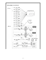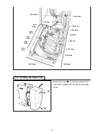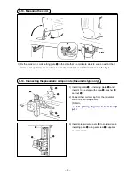
– 15 –
9
!0
!1
!2
a
!3
!3
!4
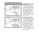
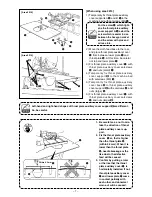
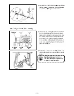
[When using area 2210]
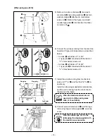
5) Remove once two setscrews
!0
, two wash-
ers (small)
!1
, two sprng washers
!2
and two
washers (large)
!3
attached to mechancal
valve unt
9
. Refer to the figure, and install
2-pedal type pedal
!4
nto hole
a
of mechan-
cal valve unt
9
.
6) Connect the ar tubes comng from the machne
head and Y-type jont respectvely as descrbed
below.
•
Ar tube
!5
wth label of "1A, 2A"
/
Y-type jont
!7
connected wth the label of
"3" of mechancal valve unt
•
Ar tube
!6
wth label of "1B, 2B"
/
Y-type jont
!8
connected wth the label of
"4" of mechancal valve unt
!6
!8
!7
!5
3
1a 2a
4
1B
2B
8
!9
connector
cn1
connector
cn2
A
stop plug
stop plug
B
7) Install the ar tube comng from mechancal
valve unt "7" to
A
, and that from "8" to
B
re-
spectvely.
Install two stop plugs suppled as accessores,
and the cords comng from the control box to
the places in the figure.
When the mechanical valve is not
used, refer to [When using areas
1306, 1510 and 2206].
8) Connect solenod valve asm.
8
and the regu-
lator usng long ar tube suppled
!9
as acces-
sores.
When the cable sags, fix it to the
table using the staple supplied with
the machine as accessories.

