background image

4. Operation  34


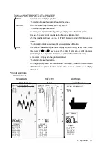
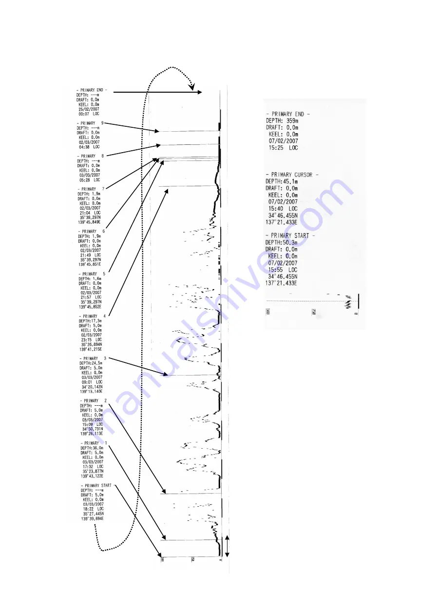
2. HISTORY print mode                                         3. LOG print mode 
       24hours history                                                  30minutes log 


1hour time mark 

Содержание JFE-680 -

Страница 1: ...80 ISO 9001 ISO 14001 Certified JAN 2019 Edition 8 CODE No 7ZPNA2012H Not use the asbestos For further information contact URL Head office http www jrc co jp eng Marine Service Department 1 7 32 Tatsumi Koto ku Tokyo 135 0053 Japan tmsc jrc co jp 81 50 3786 9201 e mail One call ...

Страница 2: ......

Страница 3: ...isplays Before attempting to operate this equipment please read this instruction manual thoroughly to ensure correct and safe operation in accordance with the warning instructions and operation procedures You are strongly recommended to store this instruction manual carefully for future reference In the event that you have an operational problem or malfunction this manual will provide useful instr...

Страница 4: ...jury to the operator or physical damage to the equipment Example Pictograms This mark is intended to alert the user to the presence of precautions including danger and warning items The picture in each mark alerts you to operations that should be carefully performed This mark is intended to alert the user to the presence of prohibited activity The picture word in beside each mark alerts you to ope...

Страница 5: ...ng may result in fire electric shock or damage Do not place any vessels containing water or other liquids or metal objects on top of this equipment If water is spilled on or metal objects fall into the equipment there is a risk of fire electric shock or damage Do not insert or remove the power cord or operate switches with a wet hand Otherwise you may suffer from an electrical shock Usage Hints ii...

Страница 6: ...ile or electric shock if you continue to use the equipment If you notice smoke unusual smells or abnormal heat coming from the equipment immediately turn off the power switch then contact JRC or its agent There is a risk of fire electric shock or damage if you continue to use the equipment There are no customer serviceable parts inside Unauthorized inspections and repairs could cause fires and ele...

Страница 7: ...toppling over resulting in injury If it is cold do not move the equipment suddenly into a warm environment and switch it on High voltage leaks due to condensation may result in damage to the equipment In such situations leave the equipment in the warm environment for about 30 minutes before switching it on When installing the equipment securely connect the earth lead to the earth terminal Failure ...

Страница 8: ... configuration of the until could cause the unit to malfunction Take care when laying the transducer cable power cable and earth lead as positioning has an affect on electromagnetic interference There is a risk of interfering with other equipment or the echo sounder being interfered with by the other equipment After installing the echo sounder turn on the power to all other equipment to check for ...

Страница 9: ...External View External View vii NO ALERT ...

Страница 10: ...ective unifies format approval standards implemented separately by each European NMEA0183 formats for the National Marine Electronics Association NMEA0183 is the format used when sending or receiving depth position water temperature ship speed and other information between marine equipment STC Sensitivity Time Control is used for reduce shallow water clutter Shallow seabed echo is strong and deep ...

Страница 11: ...ght DAY NIGHT Displaying Menu MENU Registering Setting ENT Cancelling Menu CLR Printing PRINT Stopping Buzzer ACK Up and Down Key Cursor CURSOR Right and Left Key Cursor CURSOR 4 2 Menu List 4 3 Display Setting Selecting Image Scrolling Speed Noise Suppression Interference Rejection Setting Auto Gain Setting Auto Range Setting FWD AFT Draft Setting Cursor Display 4 4 Alert Setting Setting Buzzer K...

Страница 12: ...ance Function Executing Self Test Displaying Alert Log Outputting Alert Log Deleting Alert Log Executing Line Monitor Displaying RX Monitor Displaying System No 6 3 Replacing Printer Paper 6 4 Replacing Backup Battery 6 5 Troubleshooting 6 6 Replacing Fuses 6 7 Repair Parts 7 Consider Installation 8 After sales Service 8 1 When Requesting Servicing 8 2 Recommendations for Inspection and Maintenanc...

Страница 13: ...data for last 24 hours in memory to play back the past sounding information Dual frequency mode and two transducers are available in option requires an optional equipment Conforms to the IMO Performance Standard When the depth becomes shallower than a previously set value a depth alert is issued by buzzer and LCD display When power is cut to the main unit a power fail alert is issued by buzzer and...

Страница 14: ...y AW 154F 200kHz AW 154F 50 50kHz or 50kHz A Transducer secondary NKF 341 200kHz with cable 20 30 40m NKF 345 50kHz or 50kHz A with cable 20 30 40m NKF 392C 200kHz with cable 20m Gate valve transducer NKF 393 394 200kHz with cable 20 30 40m NKF 396 50kHz with cable 20 30 40m Flush mounting Kit BRBX05351 Color MUNSELL N4 BRBX05355 Color MUNSELL 7 5BG7 2 BRBX05354 Color MUNSELL 2 5G7 2 Table mountin...

Страница 15: ...ction Equipment Outline The following shows the external dimensions of the JFE 680 1 External Dimension of JFE 680 2 Dimensions of AW 154F AW 154F 50 Matching box 1 Introduction 3 Unit mm Mass 7kg Unit mm Mass 4kg ...

Страница 16: ...lustrated below are for the standard equipment Please refer to the separately supplied drawings if your specifications are not standard 1 NKF 341 NKF 345 Installed on ship s bottom 2 NKF 392C Installed on ship s bottom 1 Introduction 4 Unit mm Mass 22kg Unit mm Mass 41kg ...

Страница 17: ...3 NKF 393 Installed on ship s bottom 4 NKF 394 Installed on ship s bottom 5 NKF 396 Installed on ship s bottom 1 Introduction 5 ...

Страница 18: ...1 5 System Configuration 1 Introduction 6 alert alert alert alert alert alert alert ...

Страница 19: ...ANEL Switches the equipment power on and off Turn on Hold down the PWR PANEL key for 3 seconds Turn off Hold down the both the PWR PANEL and the BRILL keys for 3 seconds Adjusts the control panel brilliance in power on state 8 BRILL Adjusts the screen brilliance 9 DAY NIGHT Enhances the visibility of the screen 10 PRINT Starts printing or Data output 11 RANGE Switches the depth range to shallow or...

Страница 20: ...unding echoes Note LAT LON display needs to connect position data 3 Display 8 Depth cursor By primary and secondary transducer setting dual display data will change position FWD sounding data is displayed on the right side Please see page 27 FWD 50kHz AFT 200kHz Alert Alert Alert ...

Страница 21: ...History mode History mode displays past 12hour or 24 hour depth graph and real time sounding Note LAT LON display needs to connect position data 3 Display 9 Keel height value AFT 200kHz 12hr Alert Alert E T ...

Страница 22: ...T LON display needs to connect position data 3 Display 10 A F T 2 0 0 k H z F W D 5 0 k H z By primary and secondary transducer setting dual display data will change position FWD sounding data is displayed on the right side Please see page 27 Alert Alert E T ...

Страница 23: ...r the key is pressed a white part in the bar graph increases and brightness goes up Whenever the key is pressed a black part in the bar graph increases and brightness goes down Press the CLR key or leave it for ten seconds the bar graph is not displayed Range Control RANGE RANGE The range change of this equipment is seven stages of 10 20 50 100 200 500 800m Whenever RANGE key is pressed the range ...

Страница 24: ...o sounding when the setting of sensitivity is inappropriate The reflection from sea bottom is different according to the condition of sea bottom The reflection weakens like sand and mud etc though a strong reflection returns like the bedrock It becomes impossible to recognize sea bottom when the reflection is weak and the depth value might not be displayed For this case bottom of the sea is displa...

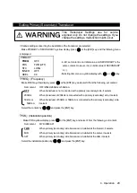
Страница 25: ...y Night Display Color DAY NIGHT Whenever the key is pressed it changes with DAY1 DAY2 NIGHT1 NIGHT2 Each color Image color and character color of DAY1 DAY2 NIGHT1 NIGHT2 can be individually set by the menu Refer to 4 5 Initial Setting Displaying Menu MENU This key uses for setting the various menu functions Detail settings are written in section 4 3 to 4 7 DISPLAY ALERT INITIAL PRINTER CONT COMMUN...

Страница 26: ...ating when keeping pressing it When the key is pressed the depth cursor is moved to the deep end and it moves accelerating when keeping pressing Depth at the cursor position is displayed on the depth cursor The cursor display is set by CURSOR menu Refer to 4 3 Display Setting The depth of the depth cursor doesn t display below the decimal point at 100m or more The depth cursor disappears when the ...

Страница 27: ...me Latitude Longitude The position where a position cursor is displayed doesn t scroll and is fixed Therefore when the history screen scrolls display information is updated When menu is displayed key When there is a hierarchy submenu below the menu of the hierarchy submenu is displayed When setting the date etc move the input position key While displaying the main menu it becomes an error However ...

Страница 28: ... OFF ON BUBBLE ALERT OFF ON PRINTER ALERT OFF ON JFE 680 DPU 414 does not have this alert INITIAL MEMORY LENGTH 12hr 24hr COLOR DAY1 SCREEN 1 2 3 4 5 6 CHARACTER 1 2 3 4 5 6 DAY2 SCREEN 1 2 3 4 5 6 CHARACTER 1 2 3 4 5 6 NIGHT1 SCREEN 1 2 3 4 5 6 CHARACTER 1 2 3 4 5 6 NIGHT2 SCREEN 1 2 3 4 5 6 CHARACTER 1 2 3 4 5 6 DEPTH DISPLAY MODE SURF TRAN KEEL PRIMARY FREQ OFF 200kHz 50kHz or 50kHz A POS FWD M...

Страница 29: ...NTER PORT OUT PRINTER PC MAINTENANCE SELF TEST CONTROL UNIT Press the ENT key to start LCD UNIT Press the ENT key to start KEY UNIT Press the ENT key to start PRINTER TEST Press the ENT key to start ALERT TEST OFF DEPTH ALARM SYSTEM ALERT ALERT LOG Press the ENT key to start ALERT LOG OUT NORMAL Press the ENT key to start PRINTER Press the ENT key to start PC Press the ENT key to start ALERT LOG D...

Страница 30: ... though 0 doesn t have the ability to decrease Select the value by and press the ENT key Interference Rejection The interference noise by another ship displayed on the screen is reduced Make INTERFERENCE a yellow display press or the ENT key and select it from the following set content Set content OFF IR1 IR2 IR3 The ability to do the interference prevention processing strengthens while switching ...

Страница 31: ... selected Make RANGE a yellow display press or the ENT key and select it from the following set content Set content AUTO MANUAL AUTO Range changes automatically like sea bottom s being always displayed at 3 5 positions of the lower side of the range scale MANUAL Set it manually with the RANGE key to the operation panel Refer to 4 1 Basic Operations When it is AUTO it starts from 10m Select the met...

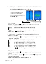
Страница 32: ...content Set content OFF ON AUTO OFF When the cursor key is operated it makes an error of the cursor without displaying it ON Whenever the cursor key is operated the cursor is displayed AUTO When the cursor key is operated the cursor is displayed for 30 seconds It doesn t display afterwards When the cursor key is pressed again it is displayed at the position Select the method by and press the ENT k...

Страница 33: ...Key Make KEYACK a yellow display press or the ENT key and select it from the following set content Set content ON OFF ON When the key on the operation panel is pressed it sounds a buzzer OFF When the key on the operation panel is pressed it doesn t sound a buzzer Select the method by and press the ENT key Setting Relay The kind of the relay contact output is selected Make RELAY MODE a yellow displ...

Страница 34: ... Select the operation by and press the ENT key DEPTH SETTING Depth where the depth alert starts is set Make DEPTH SETTING a yellow display press or the ENT key and the numerical value initial value 0 0 is displayed The numerical value becomes large when key is pressed and when key is pressed the numerical value becomes small Depth can be set up to 99 9m by a 0 1m unit When depth is set and the dep...

Страница 35: ...es or more the sea bottom lost alert is started When sea bottom was not able to be detected 40 times or more with range of 10 20 50m the sea bottom lost alert is started When sea bottom is detected after the sea bottom lost alert starts it is released Select the operation by and press the ENT key TX ALERT When the transmitter becomes abnormal the alert operation is selected Make TX ALERT a yellow ...

Страница 36: ...ed When sea bottom is detected after the bubble alert starts it is released Select the operation by and press the ENT key PRINTER ALERT When the printer becomes abnormal the alert operation is selected In the case of JFE 680 PRINTER ALERT function is the menu operates only when PRINTER MODEL SELECTION is set build in NKG 91 or NKG 901 It does not work when PRINTER MODEL SELECTION is set to DPU 414...

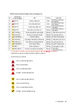
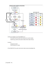
Страница 37: ...arning Depth is temporally lost 08 TX2 LEVEL Secondary transmission abnormality Warning Transmission level is low 09 RX2 LEVEL Secondary receiving abnormality Warning Receiving level is low 10 RX2 BUBBLE Secondary bubbling Warning Depth is temporally lost 11 PRINT 1 No thermal paper 1 Warning Printer paper is ended 12 PRINT DATA 1 Printer communication abnormality 1 Warning Printer data communicat...

Страница 38: ...IEC62288 ed 2 0 The Alarm sound is three short buzzer and about ten seconds intervals The Warning sound is two short buzzer and about five minutes intervals Alert corol The Alarm color is red The Warning color is orange When JFE 680 ACK key push on active state state is jump to Acknowledged state ...

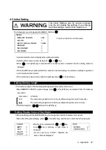
Страница 39: ...ENGTH a yellow display press or the ENT key and select it from the following set content Set content 12hr 24hr 12hr The memorizing length is set to 12 hours Memorizing interval is 30 seconds 24hr The memorizing length is set to 24 hours Memorizing interval is 1 minute Select the length by and press the ENT key Setting Display Color of Day Night When switching with the DAY NIGHT key the image color...

Страница 40: ...olor White Sea bottom color Red 8 steps 4 Gray 5 Background color Blue Sea bottom color Red Brown 8 steps 5 Navy blue 6 Background color Black Sea bottom color Amber 8 steps 6 Amber Setting Depth Display The standard when the depth value is displayed is selected Make DEPTH DISPLAY MODE a yellow display press or the ENT key and select it from the following set content Set content SURF TRAN KEEL SUR...

Страница 41: ...connected with a primary secondary side 50kHz A it selects Select the content by and press the ENT key POS Installation position Make POS a yellow display press or the ENT key and select it from the following set content Set content FWD MID AFT FWD When primary secondary side transducer is installed at the forward it selects MID When primary secondary side transducer is installed at the center it ...

Страница 42: ...ing it to an auto gain INNER Inner hull offset Make INNER a yellow display press or the ENT key and select it from the following set content Set content OFF 1 2 3 4 5 OFF The offset of inner Hull is not put on a primary secondary side 1 The offset of 4dB is set to the gain on a primary secondary side 2 The offset of 8dB is set to the gain on a primary secondary side 3 The offset of 12dB is set to ...

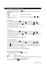
Страница 43: ...sed and when key is pressed the numerical value becomes small When the setting at the time finishes press the ENT key DIFF Time difference Make DIFF a yellow display press or the ENT key and Hour Minute Second is displayed The display of yellow is moved to the position set with key and it sets with or key When key is pressed the sign is changed from to and the numerical value become a large When k...

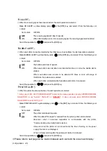
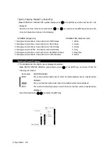
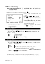
Страница 44: ...RY LOG Refer to 4 7 communication setting Select the item by or key Then press the ENT key Note Please read a detailed explanation of the each print mode item with next page PRINTER CONT PRINTER ON PRINT MODE COPY LOG BOOK PRINT OFF LOG LENGTH 10min SPEED 4800bps PRINTER MODEL SLECTION NKG 901 A present selection item is displayed with a yellow character To select items use or key to choose Press ...

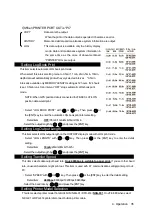
Страница 45: ...data is same one as time cursor display information LOG This printout is available only the history display mode On history display mode move time cursor by or key to select the center of LOG printout LOG graphical printout length is set by LOG LENGH menu 10min 20min 30min 1hr 2hr A time cursor is displayed in the graphical printout The direction of paper feed is time After the graphical printout ...

Страница 46: ...4 Operation 34 2 HISTORY print mode 3 LOG print mode 24hours history 30minutes log 1hour time mark ...

Страница 47: ...th or key Then press or the ENT key to enter the automatic LOG book print interval setting Detail item OFF 0 5min 1min 2min 5min 10min Select the output length by and press the ENT key Setting Log Output Length This item selects LOG output length on the HISTORY display mode with LOG print mode Select LOG LENGTH with or key Then press or the ENT key to enter the detail setting Detail item 10min 20m...

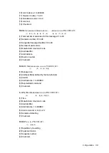
Страница 48: ...t it from the following set content Set content Ver1 5 Ver2 3 ALL Ver1 5 Setting of DEPTH DISPLAY MODE in INITIAL of the menu Only SDDBS is output for SURF Only SDDBT is output for TRAN Only SDDBK is output for KEEL Ver2 3 SDDPT is output Ver5 0 Alert serial data change to meet IEC61162 1ed5 ALL Both content of Ver1 5 and Ver2 3 are output at the same time PJRCU is output as for each setting of Ve...

Страница 49: ...splay mode DISP SURF Draft value no or sign preceding values DISP TRANS 0 0 DISP KEEL Keel height compensation sign preceding values 3 Measuring range RANGE in meters only 4 Checksum result after each ASCII code of every character between S just after and X just before is EXORed PJRCU SD x x x x x x x x xx c c hh CR LF 1 2 3 4 5 6 7 1 Water depth relative to transducer meters 2 Offset from transdu...

Страница 50: ...gnal is not good 365 secondary bottom echo signal is not good 3 Alert condition A threshold exceeded V not exceeded 4 Alert s acknowledge state A acknowledged V unacknowledged 5 Alert s description text 6 Checksum result after each ASCII code of every character between S just after and X just before is EXORed ACK xxx hh CR LF 1 2 1 Alarm number 2 Checksum On DEPTH output setting ver5 0 SDALF x x x...

Страница 51: ...r mnemonic code 6 Alert identifier 7 Alert instance 8 Revision counter 9 Checksum SDARC hhmnss ss aaa x x x x c hh CR LF 1 2 3 4 5 6 1 Release time 2 Alert specifically defined by the manufacturer 3 Alert ID 4 Alert Instance 1 to 999999 5 Rejected alert command 6 Checksum ACN hhmmss ss aaa x x x x c a hh CR LF 2 2 3 4 5 6 7 1 Time 2 Manufacturer mnemonic code 3 Alert Identifier 4 Alert Instance 1 ...

Страница 52: ...PRINT MODE Refer to 4 6 Printer Control Setting Select the content by and press the ENT key Maintenance menu operation is written in 6 2 Maintenance Function 4 8 Master Reset The buzzer sounds when turning on the power while pressing the MENU key and the CLR key at the same time and master reset is executed All set values except the date and time return to the factory shipment value When master re...

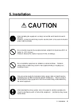
Страница 53: ...the equipment on unstable or unlevel surfaces Failure to observe this condition may result in the equipment falling or toppling over resulting in injury Take care when laying the transducer cable power cable and earth lead as positioning has an affect on electromagnetic interference There is a risk of interfering with other equipment or the echo sounder being interfered with by the other equipment...

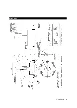
Страница 54: ...5 1 Installing the Recorder Unit Flush Mount Equipment Figure 3 1 5 Installation 42 Unit mm ...

Страница 55: ...Wall Mount Equipment Figure 3 2 5 Installation 43 Unit mm ...

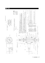
Страница 56: ...alling the Transducer The external dimensions illustrated below are for the standard equipment Please refer to the separately supplied drawings if your specifications are not standard NKF 341 5 Installation 44 ...

Страница 57: ...NKF 345 5 Installation 45 ...

Страница 58: ...NKF 392C 5 Installation 46 ...

Страница 59: ...NKF 393 5 Installation 47 ...

Страница 60: ...NKF 394 5 Installation 48 ...

Страница 61: ...NKF 396 5 Installation 49 ...

Страница 62: ...d must not contact any other connectors etc 2 Casings must be grounded securely to the ship s hull using copper plates 3 The exterior is to be grounded to the ship s hull cable bands 4 Select NC NO for Depth Alert System Alert and Power Fail Alert 5 Installation 50 alert alert alert alert alert alert alert ...

Страница 63: ...ent can be prevented from breaking down beforehand Please execute the check shown in the table regularly Maintenance and check method When you check the equipment turn off the power by all means No Item Method 1 Cleaning For the main unit wash off dirt by lightly wiping it with a dried and soft cloth Never use a plastic solvent such as thinner and benzine 2 Loosening of parts Check the screw and t...

Страница 64: ...urns to the self test menu when the CLR key is pressed after the self test result is displayed Because the screen data is rewritten when VRAM is checked the image before the check is deleted LCD UNIT Make LCD UNIT a yellow display press or the ENT key and the LCD self test starts The screen switches the color with key in single color indication of Black Red Green Blue White When the CLR key is pre...

Страница 65: ... and select it from the following set content Set content OFF DEPTH ALARM SYSTEM ALERT When DEPTH ALARM is selected and the depth alert is set according to the following procedure the test starts Menu ALERT DEPTH ALARM ALERT CONT ON ENT key Menu ALERT DEPTH ALARM ALERT SETTING A depth value that is deeper than 1 2 of the scale values is set ENT key When the sea bottom lost alert is set according t...

Страница 66: ...T a yellow display press or the ENT key and selects it from the following set content Set content NORMAL PRINTER PC NORMAL last 20 memorized alert histories are output to the depth output port PRINTER The alert history is displayed to the printer in the text The content to display is equal to ALERT LOG When PRINTER PORT OUT of menu COMMUNICATION is set to PC it becomes an error PC All the memorize...

Страница 67: ...ance menu Displaying RX Monitor Make RX MONITOR a yellow display press or the ENT key and a present situation of the receiver is displayed LEVEL Detection level of sea bottom maximum value within the range from sea bottom detection position to the lower side RANGE Range of sea bottom tracking GAIN Gain setting value When the CLR key is pressed it returns to the maintenance menu Displaying System N...

Страница 68: ...wer supply of this equipment exchange papers When the printer cover is opened while turning on the alert of NO PAPER sounds Open the paper cover by pressing the paper cover opening button Set the paper like the direction of figure Shut the cover after making the paper tip put out outside of the printer and pushing both ends of the upper paper cover A red mark of a paper slip previous notice puts o...

Страница 69: ... battery The setting data would be kept about twenty minutes by super capacitor So if you finish replacing the battery in these minutes the setting data would not need to set again Outline of battery replace 1 Turn off the echo sounder Turn off the circuit breaker Work after waiting for about 10 seconds 2 Remove the front cover of the echo sounder 3 Replace the battery 4 Set the front cover of the...

Страница 70: ...small width narrower than 5mm slotted screwdriver between the battery and the battery socket Lift the screwdriver to take off the battery Set the new battery in the battery socket The positive terminal is upside Push the battery until stayed in horizontally ...

Страница 71: ...g is too weak Make the sensitivity setting AUTO Or raise sensitivity Sea bottom is mud weak stratum Make the sensitivity setting AUTO Or raise sensitivity The oyster and the barnacle adhere to the transducer Remove the adhesion thing of the transducer at dry dock The cable disconnection of the transducer or the screw in the connecting terminal has loosened Check whether for be disconnected of the ...

Страница 72: ...pply in this equipment F2 MF51NR 250V 0 5 or equivalent 250V 0 5A For power supply alert circuit in this equipment F3 MF51NR 250V 2 or equivalent 250V 2A For built in printer power supply Fuse Positions Inside of main unit CQD 2083 1 Replacing Main Power Supply Fuse F1 As for the cause the defective cable connected with the power supply is considered Exchange fuses after defective checking the cab...

Страница 73: ...printer or Interface unit J13 is thought Remove the connecting cable of the external unit once Still when the fuse is blown because defects of an interface unit CQD 2083 a built in printer H 7HPJD0001 and wiring CQD 9142 etc are thought Request the repair 6 7 Repair Parts Parts name Type Remarks Main Unit CDJ 2338 2A CDJ 2338 2L TX RX Unit CMN 720 22 200kHz 200kHz as standard CMN 720B25 CMN 720 25...

Страница 74: ... failures and reduce the life of the equipment 1 Where liable to be splashed with water 2 Where ventilation is poor Do not coat the part of the transducer that outputs the ultrasonic waves the rubber part of the tank on the ship s bottom with the hull coating as this will deteriorate performance 7 Consider Installation 62 ...

Страница 75: ...ir will be made at your expense Details to be Submitted Name type No month and year of manufacture and serial number Nature of fault in as much detail as possible Contact details your name address and phone number etc 8 2 Recommendations for Inspection and Maintenance Depending on the conditions of usage the performance may deteriorate due to the aging of components In such conditions please consu...

Страница 76: ...ct during its normal operation in accordance with the instruction manual the dealer or JRC will repair free of charge In case that any failure is caused due to misuse faulty operation negligence or force major such as natural disaster and fire the product will be repaired with charges Repair after the Warranty Period If any defective function of the product is recoverable by repair the repair of i...

Страница 77: ...9 Disposal 9 1 Disposal of this equipment If this equipment is to be disposed please follow the guidelines of the local body governing the location at which the equipment is disposed of 9 Disposal 65 ...

Страница 78: ... 115 200 230VAC 15 50Hz 60Hz 5 less than 50W 24VDC only use for power fail monitoring Water proofing IPX2 drip proof Input nav data IEC61162 1NMEA0183 RMA RMC GGA GLL ZDA Input ACK signal IEC61162 1NMEA0183 V1 5 V2 3ACK V5 0ACN Input signals Power fail alertACK Contact input 12VDC 2 4mA current control 12VDC 1 2mA Depth alert ACK System alert ACK Contact input 5VDC 5mA current control 12VDC 1 2mA ...

Страница 79: ...Appendix Noise Bubble Noise Bubble Interruption Interference Noise from other ship Plankton layer Appendix 67 ...

Страница 80: ...ducer or surface or sea but reflected at the hull bottom or surface of sea and again reflected at the seabed toward the transducer Such multiple recording of the seabed may appear due to change of bottom quality A double or triple reflection may be sometimes recorded In any case a first reflection recording from the zero line represents a real seabed return A first second and third reflection line...

Страница 81: ...in right chart In case of a soft seabed made of mud seaweed etc they poorly reflect an ultrasonic wave to result in thin recording of the seabed with short trail The seabed quality can be more sufficiently identified with use of wider beam angle and longer pulse width Usually lower frequency is used Appendix 69 ...

Страница 82: ...above the slope when recording In case of flat seabed thin second return of seabed may sometimes appear which is slightly below the actual seabed In either case the dim or thin echoes are false and produced by side lobes of ultrasonic beam from the transducer Any false echo is thinner than and parallel to a real echo Appendix 70 ...

Страница 83: ...see and less discriminative since it tends to accompany with a false echo due to the side lobe and the inherent property of directivity In particular a seabed with abrupt slope and heavily rugged surface provided an echo very difficult to display on the recording Appendix 71 ...

Страница 84: ......

Страница 85: ......

Страница 86: ...80 ISO 9001 ISO 14001 Certified JAN 2019 Edition 8 CODE No 7ZPNA2012H Not use the asbestos For further information contact URL Head office http www jrc co jp eng Marine Service Department 1 7 32 Tatsumi Koto ku Tokyo 135 0053 Japan tmsc jrc co jp 81 50 3786 9201 e mail One call ...

Отзывы: