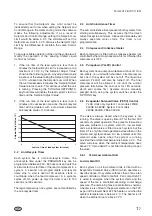
2
Operation
The operating sequence described below relates to
operation on a cooling demand start after power has
been applied, such as start-up commissioning.
When power is applied to the unit a 2 minute timer will
start. This timer also prevents instantaneous starting
after a power failure if the option POWER FAILURE
RESTART is set to AUTOMATIC under the OPTION
key.
If the option POWER FAILURE RESTART is set to
MANUAL under the OPTION key the unit switch must be
set to OFF then back to ON to reset the unit lockout
condition UNIT FAULT: 115VAC UNDER VOLTAGE.
For a unit to run, the unit switch and the software system
switches under the option key must be set to on, any
remote cycling contacts must be closed, the 'Daily
Schedule' must be scheduling the unit on, and a
temperature demand must be present. The status
message will read 'FLOW SWITCH OPEN' for 30
seconds after which a contact closes to start the
evaporator pump. On the closing of the flow switch the
remaining time on the 120 second anti-recycle timers
will be displayed.
At the end of the 2 minute timer, the microprocessor will
check for cooling demand. If all conditions allow for a
start, the first compressor on the lead system will start
and the liquid line solenoid will open. Coincident with the
start, the anti-coincident timer will be set and begin
counting downward from '60' seconds to '0' seconds.
If the unit is programmed for 'Automatic Lead/Lag
Control', the system with the shortest average run-time
of the compressors will be assigned as the 'lead'
system. A new lead/lag assignment is made whenever
all systems shut down.
After 1 minute of compressor run time, the next
compressor in sequence will start when a system has to
load. Additional compressors will be started at 60
second intervals as needed to satisfy temperature load.
If demand requires, the lag system will come on with the
same timing sequences as the lead system. However
the lead system must be running for a minimum of 5
minutes before the lag system will be allowed to run.
As the load decreases below the 'SETPOINT', the
compressors will be shut down in sequence. This will
occur at intervals of either 30, 15 or 10 seconds based
on the liquid temperature as compared to 'SETPOINT',
and control mode.
When the last compressor in each system is to be
cycled off, the system will initiate a pump-down. On a
non-safety, non-unit switch shutdown, the YLLSV will be
turned off, and the last compressor will be allowed to run
until the suction pressure falls below the suction
pressure cut-out or for 180 seconds, which ever comes
first.
2.1
Capacity Control
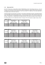
The control system will evaluate the need for cooling by
comparing the actual leaving chilled liquid temperature
to the desired 'SETPOINT', and regulate the leaving
chilled liquid temperature to meet that desired
'SETPOINT'.
The leaving chilled liquid 'SETPOINT' is the
temperature the unit will control to /- the
'RANGE'. The Setpoint High Limit is the 'SETPOINT'
plus the 'RANGE'. The Setpoint Low Limit is the
'SETPOINT' minus the 'RANGE'.
The 'RANGE' setting takes into account the number of
compressors on the unit and the temperature difference
between leaving (LCHLT) and return (RCHLT) chilled
liquid at full load (refer to Section 7.1 for details).
Each system has its own anti-recycle timers. The
anti-recycle time under the PROGRAM key can be
programmed between 240 and 600 seconds and sets
the minimum start-to-start time of the lead compressor
in a system. Due to lead lag rotation in a system,
consecutive lead compressor starts are not with the
same compressor. A second non-programmable
anti-recycle timer, stop to start is fixed at 90 seconds,
starts to countdown when the lead compressor in a
systems cycles off.
1
-
5
Form 201.26.OI1(11/09)
High Limit
Lea
ving
Liquid
T
e
mp
.
C
ut-out
(LL
T
C)
LL
TC
+
0
.6°C
Leaving Chilled Liquid Temperature
6.4°C
6.7°C
7.8°C
10
s
unloading
Low Limit
SETPOINT
10
s
unloading
60
s
loading
30
s
unloading
5.8°C
15
s
unloading
(no compressor staging)
8.9°C
RANGE
RANGE


