9
OPTIONAL SOFT START
Always isolate the unit supply before
removing the compressor motor terminal
box covers. On compressors with soft
start fitted phase L2 of the starter is
uncontrolled and thus the motor terminals
will be LIVE even with the compressor
OFF, unless the unit supply is isolated.
Optional soft start is fitted to the last compressor to start
in each system. The soft starter controls the inrush
current by switching the voltage to the compressor
motor phases LI and L3. The starter characteristics are
specifically matched to the needs of the scroll
compressors to ensure trouble free starting and to meet
lubrication requirements by acceleration to full speed
within 0.8 of a second. At the end of the voltage ramp up
time an internal bypass contactor will operate.
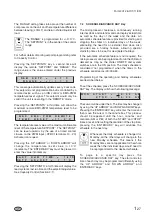
The soft starter is provided with two status LED's:
READY light will be ON as soon as the control circuit
supply is turned ON. During the start-up ramp the
READY light will flash, but the flashing may not be
detectable due to the short ramp up time. The READY
and BYPASS lights will be on when the compressor is
running.
9.1
Diagnostics
If the READY light is OFF check the control supply 110V
to soft starter terminal A1 and A2.
READY light On No BYPASS light ON, compressor
expected to start. Check for 110V on soft starter
terminals 1(IN) and A2. Check for three phase voltage,
soft starter terminals 1, 2 and 3. With the control panel
isolator OFF check wiring to compressor motor and
compressor motor windings.
Due to vibration during transport the soft
starter internal bypass contactor may be in a
undefined state. If the following procedure is
not followed this may result in the compressor
momentarily starting when the unit power is
first turned on.
IMPORTANT
During commissioning or if the soft start is replaced
the following procedure MUST BE PERFORMED.
1. With the unit switch and unit switch disconnect set to
OFF to isolate the unit, remove the fuses from the
compressors fitted with a soft starter.
2. Turn ON the unit switch disconnect to turn on the
unit supply and thus apply control circuit voltage to
soft starter terminals A1 and A2.
3. Turn OFF the unit disconnect switch and refit the
compressor fuses.
YCWL UNITS ONLY
Three Way Valve Signal
In some applications, on initial start, where the cooling
tower liquid can be cold, the YCWL can trip on low
pressure. To overcome this issue an output is provided
which can be used by the customer to control a 3-way
valve to by pass some of the condenser liquid flow
(reduce the liquid flow into the condenser) to increase
the YCWL's operating pressure.
Under the program key there are the following
associated settings
Operation
During the first six minutes of YCWL run time, with all the
compressors in a system running, if the return
condenser liquid temperature falls below the
Programmed 3-Way valve Return Liquid Temperature
Setpoint and the differential pressure between
discharge and suction is less than the programmed
3-Way Valve Pressure Differential Setpoint, the 3-way
value output is set to the 3-Way Value Voltage Setpoint.
The customer should use this voltage to set the 3 way
valve to reduce flow to the condenser.
Customer terminal block -XTBC1 terminal 52 and 53.
At the then end of the 3-Way Valve On Time, the 3-Way
value output will fall to zero and the customers valve
should operate as normal.
1
-
34
Form 201.26.OI1(11/09)
PROGRAM
LOW
LIMIT
HIGH
LIMIT
DEFAULT
3-WAY VALVE RLT
TEMP SETP (°C)
12.8
18.3
15.6
3-WAY VALVE PRESS
DIFF SETP (Barg)
6.9
9.6
6.9
3-WAY VALVE VOLTAGE
SETPOINT (Vdc)
4
7
5
3-WAY VALVE ON TIME
(sec)
180
600
300


