2.7
Lead/Lag Control
The chiller may be set up for AUTO or MANUAL
lead/lag. This is accomplished by programming the
option under the 'OPTIONS' key.
When AUTO lead/lag is used, the microprocessor
attempts to balance run time between the systems. A
number of conditions can occur which will prevent this
from happening. Factors determining lead/lag selection
and the resulting lead/lag determination are:
The microprocessor automatically defaults the lead to
system 1 and the lag to system 2 if both systems are
ready to start (Anti-recycle Timers timed out) and the
systems have equal run time.
If both systems are waiting to start (Anti-recycle timers
have not timed out), the microprocessor will assign the
lead to the system with the shortest anti-recycle time to
provide cooling quickly.
If the lead system is locked out, faulted and waiting to
restart the lag system is swapped to the lead.
MANUAL lead/Lag selection will be automatically
overridden by the microprocessor to allow the lag
system to automatically become the lead anytime the
selected lead system shuts down due to, lead system
faults.
Automatic switch over in MANUAL mode is provided to
try to maintain chilled liquid temperature as close to
‘SETPOINT’ as possible.
2.8
Condenser Coil Fan Control
(YLAA & YLAE Units)
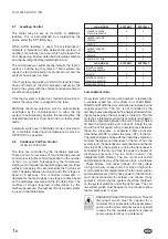
The fans are controlled by the discharge pressure.
There are two to four steps of fan discharge pressure
control plus step time control dependant on the number
of fans in a system. Subsequent to the compressor
starting, and if required by the discharge pressure, there
will be a time delay of 5 seconds before the first fan can
start. The delay between turning on and off fan stages is
fixed at 5 seconds. The controller increments or
decrements the fan stage by one stage at a time based
on the discharge pressure and the fan delay time. The
number of stages required is determined by the
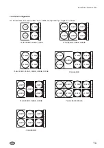
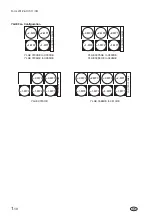
discharge pressure. The number of fans in each system
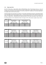
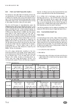
is given in the table below.
YLAA MODEL
SYSTEM 1
SYSTEM 2
0180SE to 320SE
0195HE to 0260HE
2
2
0360SE, 0400SE
0300HE
3
2
0390HE
4
2
0435SE, 0485SE
0350HE
3
3
0440HE
4
3
0455HE, 0515HE
4
4
YLAE MODEL
SYSTEM 1
SYSTEM 2
0190SE to 330SE
0195HE to 0265HE
2
2
0315HE
3
2
0375SE to 0490SE
0355HE to 0405HE
3
3
0465HE to 0510HE
4
4
Low Ambient Units
On systems with 2 or 3 fans, fan number 1 is replaced by
a variable speed fan. On system 2 of YLAA180SE,
195HE and 210SE the two small fans are replace by one
variable speed fan. The fan is not controlled by the
discharge pressure stages but is energized directly from
the fan fuses when the unit power is turned on. The fan
motor has a integral invertor which controls fan speed to
maintain a pressure between 18 and 22.5 barg. Below
18 barg the fan should be off, above 22.5 barg the fan
should be at full speed, with a linier response between
these two pressures. A separate 4-20ma pressure
transducer (-BFDP) is wired via a relay (-KF1) to the fan.
The relay energizes along with the liquid line solenoid to
connect the pressure transducer to the fan. When the
system is off, the transducer is disconnected and the fan
will stop. When the system is running the transducer is
connected to the fan and thus fan speed is based on
discharge pressure. The fan motor invertor has
integrated EMC filtering. The fan motor will restart
automatically after any of the following trips - Line failure
- Phase Failure - Line under Voltage - DC link voltage
too high or to low - Locked rotor. For trips on high motor
or motor electronics temperatures the fan motor will not
automatically reset. The 3 phase power to the fan motor
must be disconnected for at least one minute. If any
system is still running the system should be shutdown
on the system switches under the option key. The unit
disconnect switch must be open for one minute to allow
the fan electronics to reset.
DANGER OF ELECTRICAL SHOCK. The unit
disconnect switch must be opened for a
minimum of 5 minutes before the panel power
section or fan motor terminal cover is opened
to allow the the variable speed fans internal
power supply to decay to a safe level.
1
-
8
Form 201.26.OI1(11/09)


