1.1.9
Load Limiting
Load Limiting prevents the unit from loading beyond a
desired value. 4 compressor units can be load limited to
50% of the compressors by allowing only 1 compressor
per system to run. 5 compressor units can be load
limited to 40% or 80% of the compressors. The 80%
would allows a up 2 compressors per system to run and
the 40% limit would allow up to 1 compressor per system
to run. 6 compressor units can be load limited to 33% or
66% of the compressors. The 66% limit would allow up
to 2 compressors per system to run, and the 33% limit
would allow up to 1 compressor per system to run. No
other values of limiting are available.
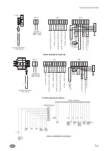
The unit can be load limited through remote
communication via an ISN, Bacnet or Modbus, or
through closing contacts connected to the Load Limit
terminals 13 and 21 and PWM inputs terminals 13-20.
(-ARB circuit board on YLAA and YLAE units, -XTBC1
on YCWL/YCRL units). Stage 1 of load limiting involves
closing the Load Limit input. Stage 2 of load limiting
involves closing both the Load Limit and PWM inputs.
The first stage of limiting is either 50% of unit on 4
compressor units, 80% on 5 compressor units or 66.3%
on 6 compressor units. The second stage of limiting is
only available on 5 and 6 compressor units,40% of unit
on 5 compressor units or 33% on 6 compressor units.
Remote unload when using remote contacts is available
when either REMOTE or LOCAL is selected for LOCAL /
REMOTE MODE under the OPTION key.
Simultaneous operation of Load Limiting and
EMS-PWM Temperature Reset is not possible.
However Load Limiting when using remote unload
contacts can be implemented if the analog temperature
reset is used.
1.1.10 Fan Full Speed Inhibit
(110 V circuit)
YLAE Units with Dual Speed Fans only
To reduce unit noise the fans can be limited to run at a
maximum step of all fans in star (reduced speed) i.e. fan
full speed is inhibited. Connect a customer voltage free
contact to terminals 33 & 34 (-ARB circuit board).
The contact must be rated for 110 Vac, connecting
wiring does not need to be run in screened cable. When
the contact is closed fan full speed inhibit is in effect.
1.1.11 Fan Full Speed Inhibit
(30VDC Circuit)
YLAA Units with Dual Speed Fans only
To reduce unit noise the fans can be limited to run at a
maximum step of all fans in star (reduced speed) i.e. fan
full speed is inhibited. Connect a customer voltage free
contact to terminals 13 & 16 (-ARB circuit board). When
the contact is closed fan full speed inhibit is in effect.
VOLTAGE FREE CONTACTS
A 28 Vdc or up to 254 Vac external circuit (supplied by
others) may be connected to these contacts. The
contacts are rated at 125 VA.
If any inductive load device (relay or
contactor) is connected to these contacts, the
device must be suppressed at the load with a
RC suppressor across the inductive coil.
Failure to install suppressors will result in
nuisance faults and possible damage to the
unit.
1.1.12 Chilled Liquid Pump Control
(
YCWL/YCRL and YLAA / YLAE units without
the hydro kit option)
Terminals 23 and 24 (-ARB circuit board on YLAA and
YLAE units) and 23 and 24 (-XTBC1 on YCWL/YCRL
units) close to start the liquid pump. After the "30 second
stop to start timer" has timed out, this contact is closed if
there is a 'Leaving Liquid Temperature Cutout', any of
the compressors are running, or, the daily schedule is
not calling for a shutdown with the unit switch 'ON' and
the remote stop/start input closed, terminals 13 and 14
(-ARB circuit board on YLAA and YLAE units) and 13
and 51 (-XTBC1 on YCWL/YCRL units).
The contact must be used to ensure that the
pump is running in the event of a 'Leaving
Liquid Temperature Cutout'.
The pump contact will not close to run the pump if the
unit has been powered up for less than 30 seconds, or if
the pump has run in the last 30 seconds, to prevent
pump motor overheating.
1.1.13 Alarms
Contacts are provided on -ARB circuit board on YLAA
and YLAE units and -XTBC2 on YCWL/YCRL units,
which can be used to remotely signal alarms. The
contacts are normally open (N.O.) and will close when
control power is applied to the panel, if no fault
conditions are present. When a fault occurs which locks
out a system or the unit power is lost, the contacts open.
To obtain a system alarm signal, connect the alarm
circuit to terminals 29 and 30 for No. 1 system and
terminals 31 and 32 for No. 2 system.
1.1.14 System Run Status
System run status is indicated by closure of contacts on
-ARB circuit board on YLAA and YLAE units and
-XTBC2 on YCWL/YCRL units, terminals 25 and 26 for
system 1 and terminals 27 and 28 for system 2.
1
-
4
Form 201.26.OI1(11/09)


