JOHNSON CONTROLS
39
SECTION 5 - REPLACEMENT PARTS AND KITS
FORM 50.40-OM1 (713)
ISSUE DATE: 07/17/2013
5
REFERENCE
NUMBER
PART
NAME
NUMBER
REQUIRED
PART
NUMBER
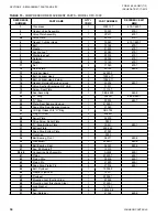
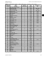
38
Seal End Plate Gasket
1
16720
39
Seal End Plate
1
16721
40
Head Pipe Plug 1/8”
3
16036
41
Half Union Elbow
1
16037
42
Flare Cap 1/4”
1
16730
43
Service Valve, Compressor Suction 7/8S.
2
16737
Service Valve, Compressor Discharge 7/8S.
1
16737
44
Dowel Pins
8
16034
Front Bushing - Crankcase
1
16733**
Rear Bushing - Crankcase
1
16734**
Complete Gasket Set
1
16816
Discharge Manifold Crossover Tube Assembly
1
16815
* Part cannot be ordered separately. Must be ordered as complete
Assembly.
** Must be line bored and reamed after pressing into crankcase.
All parts used in Model D799 same as Model 16799 except for the following:
TABLE 20 -
MODEL D799 COMPRESSOR PARTS (OLD STYLE)
DETAIL
NUMBER
PART
NAME
NUMBER
REQUIRED
PART
NO.
1
Crankcase (includes front & rear bushing)
1
16900
2
Cylinder
2
16902
Changing the Valve Plate Assembly
(See
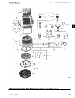
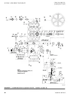
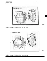
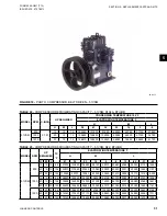
Figure 10 on page 37 and Figure 11 on page
1. Remove cylinder head bolts, cylinder head and
valve plate assembly from compressor.
2. Remove all traces of gasket material from both
the cylinder and the cylinder head flanges.
3. Thoroughly clean the cylinder head using a good
solvent as a cleaning agent.
4. Thoroughly clean the top of the pistons and the
cyl inder flange: The most efficient manner in
which to accomplish this is to bring one piston
flush with the top of the cylinder and clean the
top of the piston and approximately one-half of
the cylinder flange in one operation. This process
should be repeated for each cylinder using a good
solvent as a cleaning agent.
Do not allow any solvent to seep into
crank case oil.
TABLE 19
- COMPRESSOR REPLACEMENT PARTS – DISCONTINUED MODEL 16799 (CONT'D)
5. Place the valve plate gasket on the cylinder head
fol lowing the outline of the cylinder head itself to
insure correct gasket position. Use a thin film of
refrigerant oil to make gasket adhere to cylinder
head.
6.
Place the cylinder gasket on the cylinder flange
using a thin film of refrigerant oil to make gasket
adhere to the cylinder flange.
7. Thoroughly clean the valve plate assembly with a
good solvent.
8. Place suction reeds on the cylinder dowel pins.
9. Place the valve plate assembly on the cylinder us-
ing the cylinder dowel pins as a guide.
10. Replace the cylinder head (on which the valve
plate gasket has already been placed—See No. 4
above) and make certain the dicharge outlet is op-
posite the suction port on the cylinder.
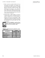
11. Replace cylinder head and tighten belts, using the
torque requirement specified for the valve plate
(See
.
Содержание YORK EASYTANK LD17584
Страница 4: ...JOHNSON CONTROLS 4 FORM 50 40 OM1 713 ISSUE DATE 07 17 2013 THIS PAGE INTENTIONALLY LEFT BLANK ...
Страница 28: ...JOHNSON CONTROLS 28 FORM 50 40 OM1 713 ISSUE DATE 07 17 2013 THIS PAGE INTENTIONALLY LEFT BLANK ...
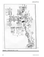
Страница 48: ...JOHNSON CONTROLS 48 FORM 50 40 OM1 713 ISSUE DATE 07 17 2013 LD17572 Figure 16 COMPRESSOR PARTS 51VSM ...


