JOHNSON CONTROLS
29
FORM 50.40-OM1 (713)
ISSUE DATE: 07/17/2013
4
GENERAL
Replacement of Filter Dryer Element
1. Unplug the RSR power cord.
2. Close valves 1, 2, 3 and 4 in the manifold (See
charge valve.
3. Remember that the system is under pressure and
safety glasses and gloves should be worn during
this operation.
4. Slowly turn each of the bolts, holding the end
plate on the canister, open one or two turns. Al-
low the reduc tion of pressure within the canister
before completely removing the end plate.
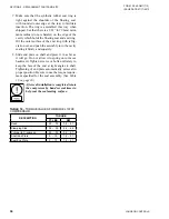
5.
Remove the old filter core from the canister and
remove the “O” ring gasket from the end plate.
Wipe the in side of the canister and the end plate
clean with a clean cloth.
6. Replace the “O” ring gasket with a new one after
wip ing it with a coating of the same type of oil
being used in the compressor.
7.
Remove the new filter/dryer element (Sporlan #
RC 4864) from the hermetically sealed wrapper.
The new element must be placed in the canis-
ter immediately since it would otherwise absorb
moisture from the sur rounding air.
8. Replace the end plate and bolt in place using an
alter nate pattern for tightening the bolts.
9. Prior to opening the compressor discharge valve,
crack valve number 3 of the manifold and slightly
break the flare connection in the tubing where it
enters the com pressor discharge. Allow the air to
be purged from the filter dryer and then tighten
the flare fitting and open the compressor discharge
valve.
Belts
The Refrigerant Recovery/Recyle Unit (RSR) com-
pressor drive belt should be checked frequently for
excessive wear and tightness. If belt is in bad condition,
it should be replaced immediately. Correct belt tension
pre vents the motor pulley from slipping, keeping the
transfer unit operating at peak efficiency.
The belt tension adjustment should be made so the belt
is taut, but not too taut to create excessive bearing loads.
Due to the pulsating load created by the compressor, the
belt tension must be greater than for a normal steady
load. Belt tension can be accurately determined with the
use of a belt tension gauge which gives a direct reading
of belt load as determined by the deflection. A tension
of 100 Ibs. is considered to be the normal belt tension.
After 36 to 48 hours of operating time, the belt should
stretch to a normal operating point and a further check
for proper tension should be made. Good alignment and
belt tension are important to insure long belt life, quiet
opera tion and to maintain top system performance.
Pulley Alignment
A very important factor in compressor operation is cor-
rect pulley alignment. The compressor pulley must be
in perfect alignment with the motor pulley and it is im-
portant that the shaft key is in place on the shaft and the
pulley bolt drawn tight, when installing a pulley. The
pulley alignment may be checked by holding a 1/2”
rod –2 or 3 feet long – firmly in the V groove of the
compressor drive pulley wheel and making sure the rod
falls squarely in the motor pulley grooves. A further
check may be made by seeing that the belt, as it goes
from pulley to pulley, comes off the pulley grooves
perfectly straight and that there are no side-way bends
in the belt, as it approaches or leaves the pulleys. Pul-
leys and belts must be clean and free of oil.
Adding or Changing Oil (High Pressure Units)
When the RSR is not running and the refrigerant pres-
sures have equalized, the oil should be 1/2 to 3/4 of the
height of the sight glass in the compressor oil sump.
To add oil:
1. Unplug the power cord.
2. Close the compressor discharge and suction
valves and manifold valves 1 and 4 (See
) and vent the pres sure from the
compressor. Using an oil pump, open the drain
valve on the compressor sump, and pump oil into
the compressor until it is at the proper level.
3. The type of oil should be the same as that used in
the refrigeration unit being serviced.
SECTION 4 - MAINTENANCE PROCEDURES
Содержание YORK EASYTANK LD17584
Страница 4: ...JOHNSON CONTROLS 4 FORM 50 40 OM1 713 ISSUE DATE 07 17 2013 THIS PAGE INTENTIONALLY LEFT BLANK ...
Страница 28: ...JOHNSON CONTROLS 28 FORM 50 40 OM1 713 ISSUE DATE 07 17 2013 THIS PAGE INTENTIONALLY LEFT BLANK ...
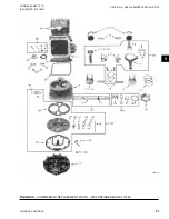
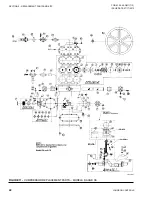
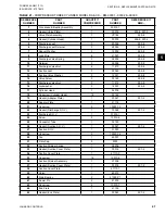
Страница 48: ...JOHNSON CONTROLS 48 FORM 50 40 OM1 713 ISSUE DATE 07 17 2013 LD17572 Figure 16 COMPRESSOR PARTS 51VSM ...

