


JOHNSON CONTROLS
8
FORM 50.40-OM1 (713)
ISSUE DATE: 07/17/2013
SECTION 1 - INTRODUCTION
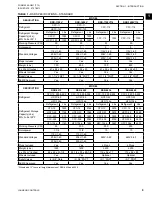
MECHANICAL SPECIFICATIONS – RSR
MODELS
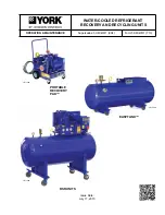
The YORK Refrigerant/Recycling System is a self-
contained package consisting of a refrigerant compres-
sor or vacuum pump, with oil separator, storage receiv-
er, heater, water-cooled condenser, filter drier and nec-
essary valves and hoses to remove, replace and distill
CFC and HCFC Refrigerants. All necessary controls
and safety devices are a permanent part of the system.
The complete system is portable, being mounted on
swivel casters with lock brakes.
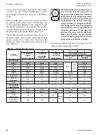
Refrigerant Compressor (High Pressure
Units)
The high pressure units for refrigerants CFC-12,
HCFC-22, CFC-500, CFC-502 and HFC-134a feature
a reciprocating compressor that is capable of pulling
a vacuum to a level which is in accordance with EPA
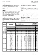
requirements (See
Refrigerant Vacuum Pump
The low pressure units for refrigerants CFC-11,
HFC-123 and CFC-114 utilize a vacuum pump to
achieve the vacuum levels required by the EPA.
The term compressor will be used synonymously with
vacuum pump throughout this document except where
specific references are necessary.
Oil Separator And Heater
Oil separator includes drain valve and 25 watt heater.
Storage Receiver
Several storage receiver sizes are available (See
). The vessel is a horizontal type with
two sight glasses installed to check liquid level. The
receiver is designed and stamped in accordance with
the ASME Boiler and Pressure Vessel Code. The ves-
sel is pitched toward the receiver drain to allow total
removal of liquid.
Valves And Hoses
The unit has permanent-mounted ball valves to allow
the unit to remove, replace, or distill refrigerant without
hav ing to break hoses to the chiller. Eight feet of heavy
duty refrigerant hoses with flare fittings are included to
allow connection to the chiller.
Heater (CFC-11, CFC-114 And HCFC-123 Only
The unit has a 1000-watt heater designed for 115V-1 -
50/60 power and capable of separating oil from refrig-
erant to less than 1000 ppm oil.
Condenser
The water-cooled condenser is a tube-in-tube design.
The condenser is permanently mounted with refriger-
ant lines piped to the system. 3/4-inch hose bib con-
nections are pro vided for field connection to the water
supply.
STORAGE RECEIVER
The receivers are ASME certified. Each contains inlet
and outlet valves and connections.
Safety Devices
A high-pressure switch is installed to protect the re-
ceiver and compressor against over pressurization. The
relief device is per ASME specifications. Float switch
cuts unit off when tank is 80% full of liquid refrigerant.
Filter Drier
The filter drier is permanently mounted on the system
so that all gas entering or leaving the receiver will be
filtered. The filter is a replaceable core type, capable of
removing moisture to less than 50 ppm.
Controls
Mounted toggle switches are used to operate the unit
and permit all safety devices to protect it.
Gauges
Unit-mounted gauges allow the technician to monitor
suction and discharge pressure of the RSR system.
Содержание YORK EASYTANK LD17584
Страница 4: ...JOHNSON CONTROLS 4 FORM 50 40 OM1 713 ISSUE DATE 07 17 2013 THIS PAGE INTENTIONALLY LEFT BLANK ...
Страница 28: ...JOHNSON CONTROLS 28 FORM 50 40 OM1 713 ISSUE DATE 07 17 2013 THIS PAGE INTENTIONALLY LEFT BLANK ...
Страница 48: ...JOHNSON CONTROLS 48 FORM 50 40 OM1 713 ISSUE DATE 07 17 2013 LD17572 Figure 16 COMPRESSOR PARTS 51VSM ...