


JOHNSON CONTROLS
31
SECTION 4 - MAINTENANCE PROCEDURES
FORM 50.40-OM1 (713)
ISSUE DATE: 07/17/2013
4
Compressor
Prior to servicing the compressor:
1. Make sure the power is disconnected.
2. Close Suction and discharge service valves.
3. Bleed refrigerant from the compressor to relieve
the air from the compressor and oil separator pres-
sure within. Pressure should be 5 psig or less prior
to opening the compressor.
Servicing Compressor
Care must be taken when servicing the compressor not
to mar, nick or scratch any of the parts. All machined
surfaces must be free of nicks or burrs to ensure a prop-
er fit and seating of gaskets. When replacing parts and
reassembly, the specified torque requirements shown
in
Bolts should all be run in until bolt heads make contact.
Final tightening should be in a sequence so that bolts
diagonally opposite are tightened and all drawn evenly
to the specified torque.
One of the most important factors in servicing com-
pressors is cleanliness. Extreme care should be taken
to keep foreign material from entering the compressor
when it is open. All old gaskets should be replaced.
Any old gasket material ad hering to the parts should be
carefully removed. Reusable parts should be cleaned
in a solvent.
Checking Compressor for Performance
If the compressor appears not to perform properly, the
fol lowing checks should be made:
1. Allow the suction pressure to build up to a mini-
mum of 30 psig. Thoroughly check the compres-
sor and all refrigerant holding components for
leaks.
2. If no leaks are found, close the suction service
valve and run compressor until compressor suc-
tion pressure is 0 psig.
3. Stop compressor. Observe discharge pressure and
if it remains constant the discharge valves of the
valve assem bly are holding properly. If pressure
drops more than 5 Ibs. (34.5 kPa) in one minute,
this indicates the discharge valves of the valve
assembly are leaking and should be replaced. If
in doubt as to whether the discharge valves leak,
turn the compressor over by hand. If pressure rises
and falls with each revolution this will confirm the
discharge valve leak.
4. If the discharge valves are holding then check suc-
tion valves of the valve assembly.
5. Back seat (open) the discharge service valve, with
the service suction valve closed, run compressor
until a vacuum of 25” (85 kPa) is reached. Failure
of a compressor to reach 25” (85 kPa) vacuum indi-
cates leaky suction valves. All compressors should
pump a 25” (85 kPa) vacuum against normal head
pressures.
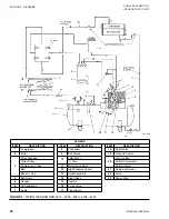
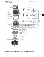
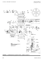
COMPRESSOR MODEL CFC 1000
Servicing of Shaft Seal
(See
)
When servicing the shaft seal, extreme care must be
taken when removing or installing the parts to prevent
damage to the lapped surfaces and other seal parts. The
portion of the shaft upon which the seal fits must be
free of scratches, burrs and dirt, and the seal housing
cavity must be clean.
Removal of Seal Assembly
1. Remove the sheave and key from the shaft.
2. Remove the seal retainer plate bolts and gently re-
move the seal plate.
3. Remove the seal assembly from the shaft.
4. Clean all parts to be reused.
Содержание YORK EASYTANK LD17584
Страница 4: ...JOHNSON CONTROLS 4 FORM 50 40 OM1 713 ISSUE DATE 07 17 2013 THIS PAGE INTENTIONALLY LEFT BLANK ...
Страница 28: ...JOHNSON CONTROLS 28 FORM 50 40 OM1 713 ISSUE DATE 07 17 2013 THIS PAGE INTENTIONALLY LEFT BLANK ...
Страница 48: ...JOHNSON CONTROLS 48 FORM 50 40 OM1 713 ISSUE DATE 07 17 2013 LD17572 Figure 16 COMPRESSOR PARTS 51VSM ...