


JOHNSON CONTROLS
35
SECTION 5 - REPLACEMENT PARTS AND KITS
FORM 50.40-OM1 (713)
ISSUE DATE: 07/17/2013
5
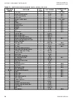
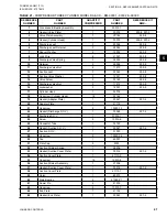
TABLE 16 -
COMPRESSOR TORQUE SPECIFICA-
TIONS – MODEL CFC-1000
DESCRIPTION
CAPSCREWS AND BOLTS
THREAD
SIZE
TORQUE
STD.
(FT. LBS)
METRIC
(KM)
Rod Cap Screw
1/4-20
7-8
0.96–1.1
Valve Plate Screw
1/4-28
6
0.82
Oil Filler Plug
1/8 NPT
10–15
1.38–2.0
Bearing Retainer
1/4-28
6–7
0.82–0.96
Seal Retainer Plate
10-32
54–78
0.62–0.89
Cylinder Head
5/16-24
24–28
3.3–3.8
Flywheel Capscrew
5/16-24
24–28
3.3–3.8
Mounting Foot
3/8-16
15–20
2.0–2.7
Rotolock Valve
—
30–40
4.1–5.5
Oil Sight Glass
1 1/8-18
UNEF
75
10.4
TABLE 17 -
COMPRESSOR PISTON SELECTIVE
FITS
SELECTIVE FITS
CLEARANCE
INCHES
MM
Piston Pin to Piston
.0002/.0003
.005/.007
Piston Pin to Rod
.0002/.0003
.005/.007
Piston to Cylinder
.0032/.0042
.081/.106
Rod to Shaft Journal
.0007/.0015
.018/.038
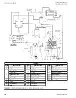
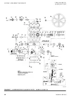
COMPRESSOR REPLACEMENT
If the compressor fails and it is evident that the crank-
shaft bearings, connecting rods or pistons have been
damaged, the entire compressor should be replaced.
TWIN CYLINDER MODEL CFC1000
Compressor Rotation: Either Clockwise or Counter-
clockwise.
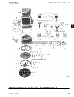
Listed on
are the part numbers
and part names for each component in our belt-driven
compressor Model CFC 1000. These part numbers and
part names are indexed by reference numbers as shown
in
which shows the layout of
each part.
Please note that BMK-(number) refers to a replace-
ment kit of parts as follows:
BMK683-7
Gasket Kit
BMK679-1
Valve Plate Kit
BMK665-8
Seal Kit
BMK680-6
Crankshaft and Bearing Kit
BMK695-1
Piston and Rod Kit (Standard)
BMK695-2
Piston and Rod Kit (.020 Oversize)
BMK679-3
Valve Plate Kit (Cad & Nickel Plated)
Components in the valve plate kit, seal kit, piston and
rod kit and the crankshaft kit are shown within an area
enclosed by a line on the drawing on
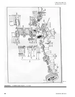
COMPRESSOR MODEL 16799 (RST-2240,
RSR-2250 & RP-2400)
Shaft Seal Assembly Servicing
When servicing the shaft seal, extreme care must be
taken when removing or installing the parts to prevent
damage to the lapped surfaces and other seal parts. The
portion of the shaft upon which the seal fits must be
free of scratches, burrs and dirt, and the seal housing
cavity must be clean.
Removal Of Seal Assembly
1. Remove the sheave and key from the shaft.
2. Remove the seal retainer plate bolts and gently re-
move the seal plate.
3. Remove the seal assembly from the shaft.
4. Clean all parts to be reused.
Installation Of Seal Assembly
1. Check all surfaces to make certain nicks and burrs
do not exist.
2. Wash all parts of the seal assembly in clean YORK
Refrig eration Oil.
3. Oil shaft with refrigeration oil to allow new seal to
be pushed into position.
4. Put on spring holder and spring. Be sure that
spring is centered in spring holder.
5. Slide the assembly along shaft just far enough to
center in spring and hold spring in place. Do not
compress the spring at this stage.
6. Before putting on end plate, thoroughly clean and
oil with 300 viscosity refrigeration oil on both seal-
ing faces. Install floating seats in end plate as fol
-
lows:
Содержание YORK EASYTANK LD17584
Страница 4: ...JOHNSON CONTROLS 4 FORM 50 40 OM1 713 ISSUE DATE 07 17 2013 THIS PAGE INTENTIONALLY LEFT BLANK ...
Страница 28: ...JOHNSON CONTROLS 28 FORM 50 40 OM1 713 ISSUE DATE 07 17 2013 THIS PAGE INTENTIONALLY LEFT BLANK ...
Страница 48: ...JOHNSON CONTROLS 48 FORM 50 40 OM1 713 ISSUE DATE 07 17 2013 LD17572 Figure 16 COMPRESSOR PARTS 51VSM ...