JOHNSON CONTROLS
32
FORM 50.40-OM1 (713)
ISSUE DATE: 07/17/2013
SECTION 4 - MAINTENANCE PROCEDURES
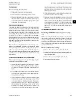
Installation of Seal Assembly
1. Check all surfaces to make certain nicks and burrs
do not exist.
2. Wash all parts of the seal assembly in clean oil of
the same type being used in refrigeration unit be-
ing serviced.
3. Push the seal assembly onto the shaft. Move the
seal assembly in and out on the shaft to ensure a
good seal.
4.
Place a very light film of oil on the matching met
-
al faces where the “O” ring is to be placed. Place
the “O” ring in the groove.
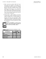
5. Place the seal retainer plate in position with the pol-
ished surface facing the compressor. Turn the bolts
in evenly while rotating the shaft, making sure that
the clearance between the shaft and the hole in the
retainer plate is the same all around the circumfer-
ence. If clearance is not the same all around, gently
tap the seal retainer plate until it is so. Tighten bolts
diagonally opposite to the required torque (See
Servicing Valve Plate and Head
In removing the head, extra care should be taken not to
damage the sealing surfaces.
Removal of Head and Valve
(See
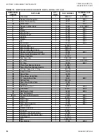
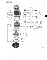
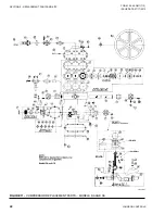
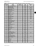
1. Remove the four bolts (15) from cylinder head.
The four bolts removed are longer in
length than the remaining head bolts.
2. Remove the remaining bolts in the cylinder head
and remove the valve plate (3), and cylinder head
from the crankcase by tapping lightly under the
ears which ex tend from the valve plate. If the head
and valve plate adhere, hold the head and tap the
valve plate ears away from the head with a soft
hammer. Do not hit or tap the head to separate the
head and valve plate because damage to the head
may result.
3. All gasket material adhering to the head, valve
plate, or cylinder, should be carefully removed in
such a manner that the machined sealing surfaces
are not scratched or nicked.
Installation of Head and Valve Plate
1.
Apply a thin film of clean
YORK Refrigeration
oil on the area of the crankcase to be covered by
the cylinder gasket. Place the cylinder gasket in
position on the cylinder so the dowel pins in the
crankcase go through the dowel pin holes in the
cylinder gasket.
2.
Apply a thin film of clean Y
ORK Refrigeration
oil to the top and bottom valve plate area to be
covered by gas kets. Place the valve plate in posi-
tion on the cylinder gasket so the discharge valve
assemblies (i.e. the smaller diameter assemblies
with the retainer over the valve reed) are facing up
and the locating dowel pins go through the dowel
pin holes in the valve plate.
3. Place the head gasket (4) in position on the valve
plate (3) so the dowel pins go through the dowel
pin holes in the gasket.
4.
Apply a light film of clean
YORK Refrigeration
oil on the machined surface of the cylinder head
which matches the head gasket. Place the head on
the cylinder head gasket so the dowel pins go into
the dowel pin holes in the head.
5.
Apply a thin film of clean
YORK Refrigeration
oil to the service valve flanges on the head and on
the service valve flange. Place a service valve gas
-
ket in position on the cylinder head service valve
flanges. Place the service valve in position on the
proper service valve ports and insert the longer
bolts through the service valve mount ing pads, the
head, end valve plate and in the crankcase.
6. Insert the remaining head bolts and run in all the
bolts so the bolt heads make contact. Tighten the
head and service valve bolts to the required torque,
by tightening the service bolts first. Then tighten
the remaining in a sequence so bolts diagonally op-
posite each other are evenly drawn to the specified
torque.
Содержание YORK EASYTANK LD17584
Страница 4: ...JOHNSON CONTROLS 4 FORM 50 40 OM1 713 ISSUE DATE 07 17 2013 THIS PAGE INTENTIONALLY LEFT BLANK ...
Страница 28: ...JOHNSON CONTROLS 28 FORM 50 40 OM1 713 ISSUE DATE 07 17 2013 THIS PAGE INTENTIONALLY LEFT BLANK ...
Страница 48: ...JOHNSON CONTROLS 48 FORM 50 40 OM1 713 ISSUE DATE 07 17 2013 LD17572 Figure 16 COMPRESSOR PARTS 51VSM ...


