JOHNSON CONTROLS
15
SECTION 2 - OPERATION
FORM 50.40-OM1 (713)
ISSUE DATE: 07/17/2013
2
Only the dedicated storage vessel and interconnecting
hose set supplied with the RSR unit can be used for the
hookup.
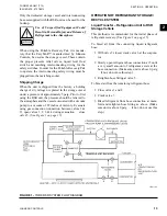
Use of Unspecified Equipment Could
Result in Personal Injury and Release of
Refrig erant to the Atmosphere.
When using the Portable Recovery Pak, it is manda-
tory that the EasyTank™, manufactured by Johnson
Controls, be used as the storage vessel. These contain
the proper pressure relief valves, liquid level float
switch and matching intercon necting wiring for the
safety switches. In order for the Por table Recovery Pak
to operate, the interconnecting safety wiring must be
plugged into the matching socket.
Shipping Charge
When the unit is shipped from the factory, a holding
charge of dry nitrogen is placed in the storage vessel
under a pres sure of approximately 5 psig. Prior to first
using the RSR unit, the pressure should be relieved to
the atmosphere and the vessel evacuated with a vacuum
pump to a vacuum of 29 inches of mercury. Evacuate
using gas connection (con nection between valves 1 &
2), open valves 1, 2, 3, & 4 during evacuation – close
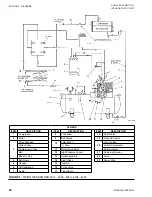
valve 5. (See
FIGURE 1 -
YORK RSR SYSTEM FLOW DIAGRAM
LD01105
OPERATION OF REFRIGERANT STORAGE/
RECYCLE SYSTEM
Liquid Transfer – Refrigeration Unit to RSR
Storage Vehicle
This method is recommended for the initial phase of
refrig erant recovery. (See
To bleed air from the connecting liquid refrigerant
hose:
1. With valve 5 closed, crack valve 6 at the evapora-
tor.
2. Slowly open refrigerant hose connection at 5 until
a very small amount of refrigerant exists at the
hose connection. (Make sure unit is above 0 psig
– if not, do not use this step.)
3.
Retighten hose fitting at valve 5.
To bleed air from the remaining refrigerant hose:
1. Close valves 1 and 2.
2. Crack valve 7.
3. Bleed refrigerant from hose con nection at mani-
fold and retighten hose fitting as above. (Make
sure unit is above 0 psig – if not, do not use this
step.)
Содержание YORK EASYTANK LD17584
Страница 4: ...JOHNSON CONTROLS 4 FORM 50 40 OM1 713 ISSUE DATE 07 17 2013 THIS PAGE INTENTIONALLY LEFT BLANK ...
Страница 28: ...JOHNSON CONTROLS 28 FORM 50 40 OM1 713 ISSUE DATE 07 17 2013 THIS PAGE INTENTIONALLY LEFT BLANK ...
Страница 48: ...JOHNSON CONTROLS 48 FORM 50 40 OM1 713 ISSUE DATE 07 17 2013 LD17572 Figure 16 COMPRESSOR PARTS 51VSM ...

