


JOHNSON CONTROLS
36
FORM 50.40-OM1 (713)
ISSUE DATE: 07/17/2013
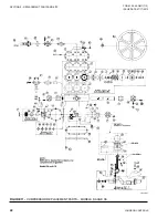
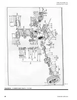
SECTION 5 - REPLACEMENT PARTS AND KITS
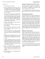
7. Make sure that the synthetic rubber seat ring is
tight against the shoulder of the floating seat,
with rounded outer edge at the rear to facilitate
insertion. The ring is assembled this way when
shipped. See that there is a 1/32” (0.79 mm) mini-
mum radius (do not chamfer) on the edge of the
cavity which holds the floating seat and seat ring.
Oil the outer surface of the seat ring with refrig-
eration oil, and push the assembly into the cavity
seating it firmly and squarely.
8. Slide end plate on shaft and press it in as far as
it will go. Do not allow it to spring out or move
backward. Tighten screws or bolts uniformly to
keep the face of the seat at right angles to shaft.
Tightening of end plate automatically sets seal in
proper position. Be sure to use the torque require-
ment specified for the seal assembly. (See
)
After seal installation is completed, rotate
the compressor by hand several times to
help seat the seal mating surface.
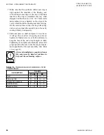
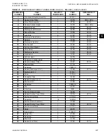
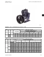
TABLE 18 -
TORQUE VALUES FOR MODEL 16799
COMPRESSOR
DESCRIPTION
TORQUE
FT. LBS.
KM
Head
25 – 30
3.4 – 4.1
Clamping Stud
32 – 35
4.4 – 4.8
Cylinder to Crankcase
25 – 30
3.4 – 4.1
Shaft End Plate
9 – 15
1.2 – 2.1
Seal End Plate
9 – 15
1.2 – 2.1
Содержание YORK EASYTANK LD17584
Страница 4: ...JOHNSON CONTROLS 4 FORM 50 40 OM1 713 ISSUE DATE 07 17 2013 THIS PAGE INTENTIONALLY LEFT BLANK ...
Страница 28: ...JOHNSON CONTROLS 28 FORM 50 40 OM1 713 ISSUE DATE 07 17 2013 THIS PAGE INTENTIONALLY LEFT BLANK ...
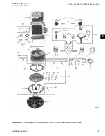
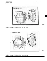
Страница 48: ...JOHNSON CONTROLS 48 FORM 50 40 OM1 713 ISSUE DATE 07 17 2013 LD17572 Figure 16 COMPRESSOR PARTS 51VSM ...