background image

www.johnsonandstarley.co.uk

26

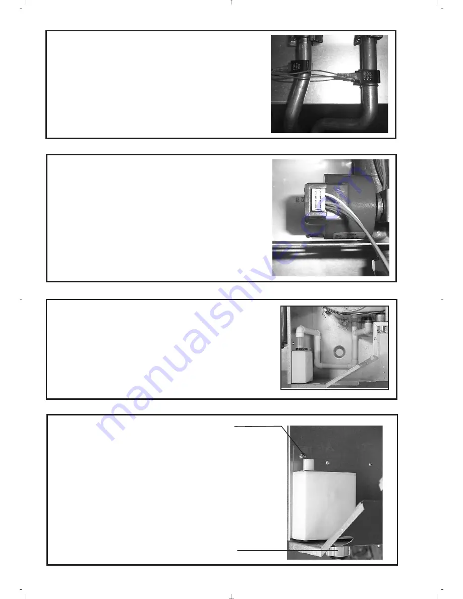
6.11 Condensate Drain

The pipe work to the siphon can be replaced once the combustion assembly
and siphon have been removed. It is a push fit onto the heat exchanger and
the plastic flue outlet. Replace with a new component in reverse order.

6.12 Condensate Siphon

Pull the condense pipe off the top of the siphon and remove the fixing screw
retaining the support bracket. Unscrew the knurled ring underneath the siphon
to free it from the sub assembly. Replace with a new component in reverse
order.

6.9 Primary Water Temperature Sensors (2 off)

Unplug the two wires from the temperature sensor to be replaced and
unclip the sensor from the pipe. Replace with a new component in
reverse order, ensuring it is fitted in the same position.

6.10 Primary Water Pressure Sensor

Close the CH flow and return valves, ensuring the drain point on the flow
valve is connected to the appliance side. Drain off the water from within
the appliance using the drain valve, unplug the electrical plug connection,
withdraw the retaining clip forwards and remove the pressure sensor.
Replace with a new component in reverse order.

Fixing screw

Knurled Ring

Содержание HE25S

Страница 1: ... johnsonandstarley co uk Model HE25S GC No 41 416 02 Installation Maintenance and Service Instructions Tel 01604 762 881 Publication ZZ1186 1 Product Identification No 87B 074 High Efficiency System Boiler BS EN ISO 9001 2000 ...

Страница 2: ...ilding Regulations Part L Part J in Scotland the boiler MUST be fitted in accordance with the manufacturer s instructions In order to demonstrate that that the installation of this appliance complies with current Building Regulations you should complete and sign the Benchmark log book Johnson Starley Ltd Rhosili Road Brackmills Northampton NN4 7LZ Tel 01604 762881 Fax 01604 767408 Sales Fax 01604 ...

Страница 3: ...uilding The appliance is controlled by fully featured microprocessor based electronics that monitor each of the operational pro cedures An LCD display indicates the operational state of the appliance which illuminates for a short period when the user control is operated This starts with the full sequence automatic ignition and continues with monitoring the demand requirements of either the central...

Страница 4: ...e an additional expansion vessel 2 2 Technical Data Table 2 1 General Data Nat Gas G20 LPG G31 Maximum Minimum Maximum Minimum Offset Pascal 3 0 Minus three Burner CO2 Case off 9 3 0 5 8 4 ref only 10 2 0 5 9 4 ref only Case on 9 5 0 5 8 6 ref only 10 4 0 5 9 6 ref only Table 2 2 Performance Data Nat Gas G20 LPG G31 Maximum Minimum Maximum Minimum CH Input Qm Net kW 25 5 7 14 25 5 7 29 Gross kW 28...

Страница 5: ...iance This allows conversion between Natural gas G20 and LPG G31 Their supply pressures are 20 mbar and 37 mbar respectively For natural gas to LPG conversion kit number NG30 complete with instructions is available For LPG to natural gas conversion kit number LPG30 complete with instructions is available Statutory Requirements The appliance must be installed in accordance with the current editions...

Страница 6: ...m to allow complete drain down The installation should be designed to operate with a flow temperature of up to 90 deg C Expansion Vessel The integral expansion vessel is pre charged to a pressure of between 0 5 and 1 0 bar This should be checked before the water system is filled Details below show the water system volume that is acceptable for this vessel If the system water volume is larger then ...

Страница 7: ...l at maximum heat input 2 7 Domestic Hot Water System Requirements Domestic hot water circuits and their components must be in accordance with the relevant standards and water sup ply regulations Further guidance and recommendations can be found in the building regulations G17 to 24 and R17 to 24 Additional Expansion Vessel if required BOILER Drain Point Bypass if required Flow Control Valve Heati...

Страница 8: ...ne and lower bracket as shown and using a light hammer tap the 8 tags over so that they form a secure assembly Lift the wall fixing plumbing jig up to the wall ensuring it is level and secure it with the screws provided The gas and water connections can now be made to the appropriate posi tions on the jig Should the heating pipes be required to exit vertically upwards there is a kit available It i...

Страница 9: ...r 95 84 73 50 For systems having a larger capacity multiply the total system capacity in litres gallons by the factor to obtain the total minimum expansion vessel capacity required litres 0 0833 0 09 0 109 0 156 Internal soil and vent stack Min Dia 22mm No restriction on length Invert Boiler Trap 75mm min 450mm min Siphon if not already part of appliance Min Dia 22mm No restriction on length Sink ...

Страница 10: ... from outside Fit the inner wall sealing disc Using the clamp arrangement join the flue to the turret ensuring all the seals are made correctly The terminal must be installed with the flue outlet at the top Brackets are provided for extended flues to locate and fix the flue in position should they be necessary Vertical Flues Flat roof Measure the distance between the appliance top and the outer su...

Страница 11: ...100 60 Concentric Flue System The appliance is supplied with a standard flue kit that includes a horizontal flue complete with terminal tur ret and fitting kit Details of optional flue components are also listed along with their resistance in Pascals in order that flue length calculations can be made Horizontal and vertical concentric flues 60 100 diam eter with balanced terminals and vertical and...

Страница 12: ...ric horizontal flue length measured from the centre line of the turret to the outside of the wall is 247mm The minimum vertical flue length is 1 14 m measured from the top of the appliance case to the top of the termi nal The minimum combined 80 twin flue length is 600mm Longer flues may be fitted however the input of the appliance will be reduced accordingly Elbows may be fitted within the flue s...

Страница 13: ...8 Horizontal Side Flue Can be left or right Standard Flue Kit 500 mm Extension Fig 3 9 Offset Vertical Flue may be offset to the rear left or right Standard Flue Kit 500 mm Extension 90o Elbow Vertical Appliance Adaptor Vertical Terminal Fig 3 10 Offset Horizontal Rear Flue Can be offset to left or right Standard Flue Kit 90o Elbow 1m Extension Fig 3 11 Vertical Flue 1m Extension 500 mm Extension ...

Страница 14: ...e LH RH or as shown Standard 90o elbow Fig 3 14 Raised Horizontal Air Vertical Flue Outlet offset Standard 90o and 45o elbows and standard vertical terminal standard 90o elbow Fig 3 13 Horizontal Air Duct Vertical Flue Duct Standard 90o elbow and standard vertical terminal Full details of twin flue components can be found in publication ZZ1191 ...

Страница 15: ... terminal 1140 mm 1 x vertical terminal assembly Vertical 1000 0018930 5 1 x support bracket Vertical Appliance Adaptor 1 x Adaptor Vertical 1000 0018990 0 90 elbow 1 x Elbow Horizontal Vertical 1000 0018980 10 45 elbow 1 x Elbow Horizontal Vertical 1000 0018970 5 Flat Roof Weather Collar 1 x Aluminium circular flat roof seal Vertical 1000 0014900 N A Pitched Roof Weather Collar 1 x Plastic lead p...

Страница 16: ...l System Controls Controls are available for outside temperature compensation and room temperature sensing These should be used to improve the heating system control They must be connected to the correct terminals as described in their own instructions A room thermostat MUST NOT be used with these controls 3 11 Fitting The Case Control Module Remove the case components from their packaging Fit the...

Страница 17: ...ODE IGNITION ELECTRODE OTC OTC OPEN THERM GAS VALVE MAINS SWITCH PUMP FAN SYSTEM PRESSURE SENSOR MMI CVBC pwm in from CVBC tacho from CVBC r r g y g y g y g y b br bk bk b bk y r r y b r g y E b N br L p p b br br r b b pk gy gy b br b b r r WIRE COLOUR CODE br brown p purple b blue pk pink bk black y yellow r red g y green yellow gy grey ...

Страница 18: ...r r b r r b b b br br b p p r b or b br b b y b r b b g y bk br or br b br L1 L2 N L3 PUMP PC CONNECTIONS MAINS SWITCH FAN PRESSURE SENSOR OPEN THERM OTC MAINS SUPPLY 230V 50Hz SPARK ELECTRODE FLAME DETECTION ELECTRODE FLUE THERMISTOR CH FLOW THERMISTOR CH RETURN THERMISTOR CVBC gy gy g y br b br or r bkbk y b r b r br L X1 X2 X3 X5 X4 N SL bk y MMI PCB pk br or br b b or br REMOVE THIS LINK TO FI...

Страница 19: ...fan speed A stylised flame will be dis played when the flame is established If ignition does not take place during the first ignition attempt there will be a further 2 attempts If the burner has still not lit a fault code will be displayed and this may be due to air being present in the gas supply Pressing the reset button will initiate a second sequence of ignition attempts When the boiler lights...

Страница 20: ... Check the gas consumption Put the appliance in test mode and connect a suitable gas analyser to the sampling point on the top of the boiler or into the flue terminal if access is possible optional test For correct boiler operation the CO CO2 content of the flue gas should not be greater than 0 004 ratio Check that the gas input is at least 90 of the nominal Clean the main burner Clean the heat ex...

Страница 21: ... removed and slowly withdraw the complete assembly including the gas inlet pipe and the case seal As the assembly is withdrawn disconnect the two electrical connections from the fan Inspect and clean the spark ignition and flame sensing electrode removing any debris and oxidiza tion and check the spark gap and position of the spark electrode and the position of the flame sensing electrode Refer to...

Страница 22: ...llowed by a two digit error code will be displayed ATTENTION The flip door at the bottom of the boiler is held in the closed posision by a concealed latch that has a push and release mechanism and is located on the upper edge of the door in the centre To gain access to the control panel apply light pressure on the upper edge of the flip door at the centre the latch will then release allowing the d...

Страница 23: ...to earth Check sensor resistance 31 Boiler flow temperature sensor open circuit Temperature sensor not connected or failed Check wiring and connections Check sensor continuity 34 Low mains supply voltage Electrical supply fault to property Faulty wiring to appliance Check incoming mains supply and wiring to appliance 35 36 Power supply fault No fault on boiler Boiler power supply should be checked...

Страница 24: ...ed door by removing the two screws and easing it to the left to disengage it from the LH side of internal casing 6 3 Control Panel complete Because of the complexity and delicate nature of the control PCB it is supplied as a complete kit with the plastic facia Remove the control panel as descibed at section 6 2 and fit the new assembly in reverse order 6 4 Electrical Switch Unscrew the metal cover...

Страница 25: ...e drain point on the flow valve is connected to the appliance side Drain off the water from within the appliance using the drain valve remove the LH painted case side and unscrew the flexible hose connection from the expansion vessel Unscrew the upper retaining bracket and remove the expansion vessel Replace with a new component in reverse order 6 8 Pressure Relief Valve Close the CH flow and retu...

Страница 26: ...bly Replace with a new component in reverse order 6 9 Primary Water Temperature Sensors 2 off Unplug the two wires from the temperature sensor to be replaced and unclip the sensor from the pipe Replace with a new component in reverse order ensuring it is fitted in the same position 6 10 Primary Water Pressure Sensor Close the CH flow and return valves ensuring the drain point on the flow valve is ...

Страница 27: ...anger Unplug the multi pin plug connections from the top of the control and the fan Remove the assembly Remove the assembly to allow the burner to be withdrawn from the heat exchanger assembly Replace with a new component in reverse order Ensure the rotational position of the burner is correct Replace with a new component in reverse order ensuring that the grommet sealing the casing is correctly p...

Страница 28: ...sembly NOTE the gas valve is factory preset and a replacement valve must only be supplied by Johnson Starley Ltd Remove the complete fan assembly as shown at section 6 18 and remove the 4 fixing screws holding the gas feed flange on the gas valve Remove the 2 fixing screws securing the venturi and gas valve to the fan and remove the assembly from the fan carefully removing the gasket Replace with ...

Страница 29: ...H Pressure Sensor Clip O Ring 7 1000 0019115 H23 617 Condensate Siphon O Rings 2 Locknut 8 1000 0709655 H23 618 Ignition Electrode Gasket Screws 2 Item Part No GC No Description 9 1000 0709665 H23 619 Detection Electrode Gasket Screws 2 10 1000 0709675 H23 620 Burner and Small Seal 11 1000 0522575 H23 621 Main Ignition Control PCB CVBC 12 1000 0522645 H23 622 Flue Temp Sensor 13 1000 0522635 H23 6...

Страница 30: ...www johnsonandstarley co uk 30 Notes ...

Страница 31: ...www johnsonandstarley co uk 31 Notes ...

Страница 32: ...www johnsonandstarley co uk 32 Johnson Starley www johnsonandstarley co uk Tel 01604 762 881 ...

Отзывы: