www.johnsonandstarley.co.uk
21
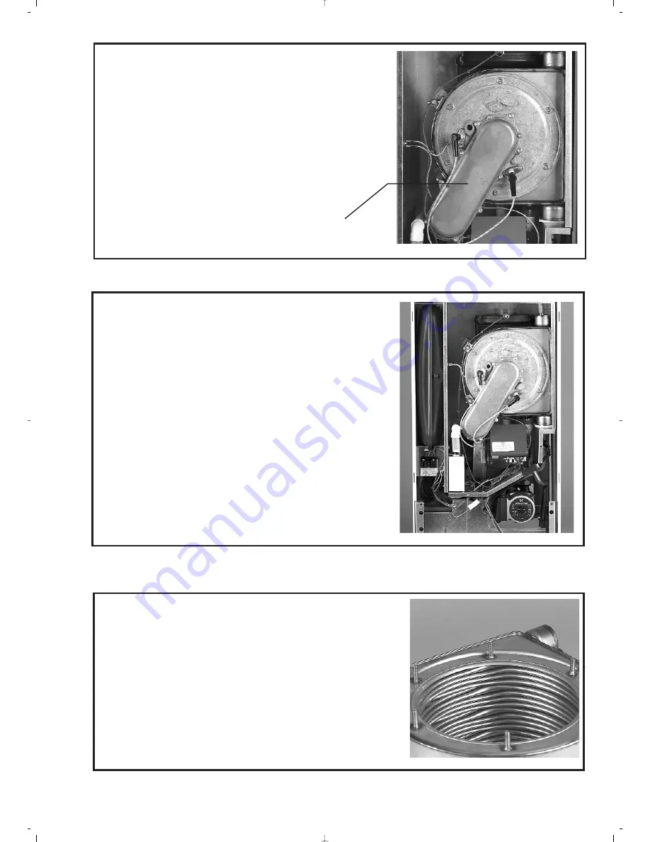
5.2 Gas/Air Duct and Internal Volume of the Burner
Remove the cover from the gas / air manifold (8 screws) and inspect
the inside of the duct and burner for debris.Clean with a soft brush if
necessary. Inspect the 'O' ring seal. Re-assemble the cover ensuring
the seal is fitted correctly.
5.3 Combustion Assembly Complete
Remove the CVBC (refer to S6.16) and disconnect the gas pipe at the
top of the isolation valve, which will already have been turned off.
Unscrew the six retaining nuts from the studs that hold the assembly to
the heat exchanger, supporting the assembly as the last one (bottom) is
removed and slowly withdraw the complete assembly, including the gas
inlet pipe and the case seal. As the assembly is withdrawn, disconnect
the two electrical connections from the fan. Inspect and clean the spark
ignition and flame sensing electrode, removing any debris and oxidiza-
tion and check the spark gap and position of the spark electrode and
the position of the flame-sensing electrode. Refer to the illustration and
adjust if necessary. Inspect the two seals and the ceramic pad on the
inside of the mounting plate and clean or replace as necessary.
5.4 Combustion Chamber/Heat Exchanger
Inspect the inside of the combustion chamber for debris. If necessary,
brush clean the inside of the tubes with a soft brush. Do not brush the
insulation at the rear, if this part is damaged it will require replacement.
Gas/Air Duct


