background image

SECTION 3 - CHASSIS & SCISSOR ARMS

3-42

– JLG Lift –

3121273

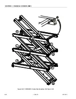
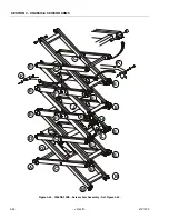
Figure 3-42.  1932RS/6RS - Scissor Arm Assembly - Ref. Figure 3-43.

A

B

I

F

C

H

C

C

E

E

D

G

Содержание 1932RS

Страница 1: ...Service Maintenance Manual Models 1932RS 6RS 3248RS 10RS 3121273 April 8 2013...

Страница 2: ......

Страница 3: ...OF THE OWNER OPERATOR B HYDRAULIC SYSTEM SAFETY It should be noted that the machines hydraulic systems operate at extremely high potentially dangerous pres sures Every effort should be made to relieve...

Страница 4: ...INTRODUCTION MAINTENANCE SAFETY PRECAUTIONS b JLG Lift 3121273 REVISION LOG Original Issue January 30 2012 Manual Revised August 1 2012 Manual Revised January 29 2013 Manual Revised April 8 2013...

Страница 5: ...ylinder Specifications 1 5 1 6 Major Component Weights 1 5 1 7 Torque Requirements 1 5 Torque Charts 1 6 SECTION 2 GENERAL 2 1 Machine Preparation Inspection and Maintenance 2 1 General 2 1 Preparatio...

Страница 6: ...Components Location 3 9 Removal All Models 3 9 Installation 3 9 3 7 Main Power Contactor Relay 3 10 3 8 Elevation Limit Switch Assembly 3 10 Location 3 10 Installation 3 10 Switch Adjustment 3 11 3 9...

Страница 7: ...4 1 4 2 Valves Theory of Operation 4 1 Solenoid Control Valves Bang Bang 4 1 Relief Valves 4 1 Crossover Relief Valves 4 1 Proportional Valve 4 1 Manual Descent Valve 4 1 4 3 Pump Motor 4 2 Pump Motor...

Страница 8: ...ty Measurement Over Long Distances 7 4 Requirements 7 4 Procedure 7 4 7 3 Applying Silicone Dielectric Compound To Amp Connectors 7 5 Assembly 7 6 Disassembly 7 7 Wedge Lock 7 8 Service Voltage Readin...

Страница 9: ...16 Tilt Sensor Installation 3 12 3 17 Tilt Sensor Switch Bubble Level 3 13 3 18 Tilt Sensor Switch Adjustment 3 13 3 19 Traction Control Circuit ZAPI Power Module 3 14 3 20 ZAPI Power Module Location...

Страница 10: ...der 4 16 5 1 Hand Held Analyzer 5 1 5 2 Diagnostic Port Location 5 1 5 3 Analyzer Menu Access Level 5 6 5 4 Analyzer Menu Diagnostics 5 7 5 5 Analyzer Menu System Test 5 8 5 6 Analyzer Menu Personalit...

Страница 11: ...ght 1 5 1 16 Cylinder Specifications 1 5 1 17 Major Component Weights 1 5 1 18 Torque Requirements 1 5 2 1 Inspection and Maintenance 2 2 2 2 Cylinder Drift 2 5 2 3 Preventive Maintenance and Safety I...

Страница 12: ...viii JLG Lift 3121273 TABLE OF CONTENTS NOTES...

Страница 13: ...GroundBearing Pressure ANSI CSA CE 130PSI 9 18 kg cm2 81PSI 5 69kg cm2 108PSI 7 6kg cm2 GroundClearance 3 1in 7 8cm 4 1in 10 3cm Table 1 2 Platform Capacities SPECIFICATION MACHINE MODEL MAXIMUM PLAT...

Страница 14: ...attery posts To disconnect power locate the RED quick disconnect connector on top of the batteries inside the battery compartment and pull halves apart Table 1 3 Machine Dimensions DESCRIPTION 1932RS...

Страница 15: ...gTemperature Output Nominal DCOutputVoltage Max DCOutputVoltage Max DCOutputCurrent Max InterlockCurrent Protection OutputReversePolarity OutputShortCircuit ACOverload DCOverload 85 265VAC 120VAC 230V...

Страница 16: ...ndard AGM 62lb 28 1kg 65lb 29 5kg Batteries combined Standard AGM 248lb 111 1kg 260lb 118 kg Table 1 10 Hydraulic Oil HYDRAULIC SYSTEM OPERATING TEMPERATURE RANGE SAE VISCOSITY GRADE 0 Fto 23 F 18 Cto...

Страница 17: ...mine proper torque value Table 1 14 Tilt Activation Setting MODEL TILT SETTING FRONT TO BACK TILT SETTING SIDE TO SIDE PLATFORM ELEVATION TILT ACTIVATION 6 IN 1932RS 6RS ALL 3 1 5 69in 1 75m 3248RS 10...

Страница 18: ...9 16 12 0 5625 0 1820 11600 110 149 80 108 120 163 98 133 18 0 5625 0 2030 12950 120 163 90 122 135 184 109 148 5 8 11 0 6250 0 2260 14400 150 203 110 149 165 224 135 183 18 0 6250 0 2560 16300 170 2...

Страница 19: ...VALUES ARE STATIC TORQUE MEASURED PER STANDARD AUDIT METHODS TOLERANCE 10 LB IN LB N m IN LB N m IN LB N m 1320 43 5 1580 60 7 1800 68 8 2860 143 16 129 15 3280 164 19 148 17 LB FT LB N m FT LB N m F...

Страница 20: ...485 335 455 315 430 7 8 9 0 8750 0 4620 41600 515 700 485 660 455 620 14 0 8750 0 5090 45800 570 775 535 730 500 680 1 8 1 0000 0 6060 51500 730 995 685 930 645 875 12 1 0000 0 6630 59700 845 1150 795...

Страница 21: ...515 315 430 7 8 9 0 8750 0 4620 41600 605 825 545 740 455 620 14 0 8750 0 5090 45800 670 910 600 815 500 680 1 8 1 0000 0 6060 51500 860 1170 775 1055 645 875 12 1 0000 0 6630 59700 995 1355 895 1215...

Страница 22: ...157 68 3 219 164 197 241 18 2 5 192 83 5 301 226 271 331 20 2 5 245 106 5 426 320 383 469 22 2 5 303 132 0 581 436 523 639 24 3 353 153 5 737 553 663 811 27 3 459 199 5 1080 810 970 1130 30 3 5 561 2...

Страница 23: ...19 5 430 385 325 20 2 5 245 152 5 610 550 460 22 2 5 303 189 0 830 750 625 24 3 353 222 0 1065 960 800 27 3 459 286 0 1545 1390 1160 30 3 5 561 349 5 2095 1885 1575 33 3 5 694 432 5 2855 2570 2140 36...

Страница 24: ...5 365 345 325 20 2 5 245 152 5 520 490 460 22 2 5 303 189 0 705 665 625 24 3 353 220 0 900 845 790 27 3 459 286 0 1315 1235 1160 30 3 5 561 349 5 1780 1680 1575 33 3 5 694 432 5 2425 2285 2140 36 4 81...

Страница 25: ...e in ser vice for 3 months or 150 hours whichever comes first out of service for a period of more than 3 months or when purchased used The frequency of this inspection must be increased as environment...

Страница 26: ...operly 9 Check for signs of leakage 10 Decals installed and legible 11 Check for proper fluid level 12 Check for chafing and proper routing 13 Check for proper tolerances 14 Properly lubricated 15 Tor...

Страница 27: ...loor 1 2 1 2 Lanyard AnchoragePoint 1 4 1 4 SCISSORARMS ScissorArms 1 2 4 1 2 4 Arm SafetyProp 1 5 1 5 Cylinder Pins PivotPins Attaching Hardware 1 1 Arm Pins WearPads AttachingHardware 1 1 CHASSISASS...

Страница 28: ...corporated 21 21 22 General Structural ConditionandWelds 2 4 2 4 AllFasteners Pins Shields andCovers 1 2 Grease andLubricateto Specifications 22 22 FunctionTestofAllSystems 22 22 Paint and Appearance...

Страница 29: ...all nuts bolts cables brackets wiring etc have been removed and that no adjacent parts are interfering Component Disassembly and Reassembly When disassembling or reassembling a component com plete the...

Страница 30: ...e or by permitting the pump to cavitate due to insufficient quantity of oil in supply tube 2 The design and manufacturing tolerances of the component working parts are very close therefore even the sm...

Страница 31: ...and oil changing procedure Lubrication Specifications Specified lubricants as recommended by the component manufacturers are always the best choice however multi purpose greases usually have the quali...

Страница 32: ...e 3 Pins should be replaced if any of the following is observed pin should be properly cleaned prior to inspection a Detectable wear in the bearing area b Flaking pealing scoring or scratches on the p...

Страница 33: ...TION 3 CHASSIS SCISSOR ARMS 3 1 MACHINE COMPONENT COVERS Figure 3 1 Machine Frame Covers All Models 1 Left Side Hydraulic Frame Cover 2 Side Cover Release Handles 3 Right Side Batteries Frame Cover 4...

Страница 34: ...one or more batteries from the machine the battery hold down bar will need to be removed See Figure 3 2 4 Remove the 2 nuts and washers from each hold down anchor at the ends of the hold down bar Rem...

Страница 35: ...SPECIFICATION OUTPUT Nominal DCOutput Voltage 24V MaximumDCOutputVoltage 33 6V MaximumDCOutputCurrent 25A MaximumInterlock Current 1A INPUT ACInput Voltage 85 265VAC Nominal ACInputVoltage 120VAC 230...

Страница 36: ...atteries are fully charged when the green light on the battery charger status panel is illuminated NOTE If the charger is left plugged in the charger will automatically restart a complete charge cycle...

Страница 37: ...nternal failure in the charger 1 Check the connections to AC power Check for AC voltage between 90 and 260 VAC at the charger 2 If the AC voltage is verified to be correct at the con nection to the ch...

Страница 38: ...ls such as an automotive charger Be sure to set this charger to the appropri ate voltage 6V per 6V battery 12V per 12V string battery 5 Flashes Over Temperature This fault indicates the charger has be...

Страница 39: ...rvice Contact JLG to get the expected battery voltage settings for the charger in question Be sure to have the charger s serial num ber and charge algorithm setting available when calling 3 5 DC TO AC...

Страница 40: ...ect BlownDCbatteryfuse s Turnoffinverter Replace fuse s withthe sametypeand rating Problem InverterIs InShut Down Batteryvoltageis below20volts Charge orreplacebattery Inverter istoohot thermal shut d...

Страница 41: ...nnect the desired connectors and components on the back of the panel Installation 1 Check that all components are installed into the panel and connected to the wiring harness 2 Insert the panel into p...

Страница 42: ...SE DAMAGE TO THE MACHINES ELECTRI CAL COMPONENTS 3 8 ELEVATION LIMIT SWITCH ASSEMBLY Location Installation Figure 3 10 Main Power Contactor Relay Location All Models 1 Main Power Contactor Relay 2 To...

Страница 43: ...mounting slots in the frame so that the roller contacts both surfaces of the scissor arm cam then tighten Switch Notes All Models The lever arm angle is to be pre set to 30 from vertical Switch Reset...

Страница 44: ...switch and arm assembly just install in the proper orientation See the LSS Service Manual 3124288 for complete ser vice information for the RS Scissors LSS system 3 10 TILT SENSOR REPLACEMENT The til...

Страница 45: ...e 4 Adjust per instructions following Tilt Sensor Switch Adjustment Procedure NOTICE PERFORM TILT SWITCH LEVELING PROCEDURE A MINIMUM OF EVERY SIX MONTHS TO ENSURE PROPER OPERATION AND ADJUSTMENT OF S...

Страница 46: ...force On level terrain the Power Module will apply as little as 14A to the fields for higher rotational speeds and better electrical efficiency The Field Windings also provide direction reversal for...

Страница 47: ...The Power Module s self diagnostics cannot detect this fault since the situation appears identical to climbing a steep grade To find the source of the difficulty disconnect main power at the batterie...

Страница 48: ...talling the new power module begin con necting the wire connectors cables to the module See Table 3 4 and Figure 3 21 7 Torque all terminal bolts to torque specifications as shown on the front of the...

Страница 49: ...r Module 1 Batteries 2 Power Module 3 Main Power Contactor Relay 4 Hydraulic Pump Motor 5 Drive Motor Stator Field Wires 6 Drive Motor Armature Brush Cables 7 To Battery Charger 8 To Battery Charger 9...

Страница 50: ...green STATUS LED that shines through the cover to indicate module health status The LED shall be illuminated when the device is powered on The LED blinks 2Hz when an internal issue is detected that c...

Страница 51: ...piercing meter probe As with the armature the field is a very low impedance and should appear to be a short circuit for an ordinary voltmeter High resistance can signal corrosion improper crimps damag...

Страница 52: ...own the cover bolts so the brake on that drive motor will disengage 5 Repeat this procedure on opposite wheel drive With both drive motor brakes now disengaged the machine can be moved manually 6 Afte...

Страница 53: ...replace if neces sary 3 Remove the two motor mounting bolts and washers 4 Gently remove the drive motor 1 NOTE Reference Figure 3 24 Drive Motor Components for part names and locations when servicing...

Страница 54: ...field connection close to the crimp connection on the motor side 6 Install the two Brake Cover Mounting Screws 15 into the threaded holes in the brake assembly and tighten to manually release the brak...

Страница 55: ...e wear and overheating Replace as necessary 6 Visually inspect the brake surfaces for excessive wear Replace Brake Assembly 11 if necessary 7 Visually inspect the Wire Harness 1 for frayed insu lation...

Страница 56: ...screws 10 Slide the strain relief of the wire harness into the slot of the terminal cover Align cover plate with groove in frame and field and affix using two cover plate screws Figure 3 25 Drive Moto...

Страница 57: ...OTE The motor may need to be rotated to line up the sun gear splines with the motor shaft splines 2 Install the two motor mounting bolts and washers Torque to 9 11 ft lbs 12 15 Nm 3 Connect the end of...

Страница 58: ...ned for improper installation or defects Some gear packages roll with more difficulty than others Do not be concerned if the gears in your unit seem to roll hard as long as they roll with consistency...

Страница 59: ...ing screws 1 4 20UNC grade 8 with at least 1 5 inches of thread length into each of the three tapped holes to force the ring gear out Be sure and alternate between the jacking screws to keep the ring...

Страница 60: ...ore of each planet gear 6 Remove the thrust washer from each planet gear 7 Remove retaining ring from output sun gear 8 Slide output sun gear out from the center of the input carrier 9 Remove the thre...

Страница 61: ...iameter push in the inner race of the bearing Apply force to the push the bearing out This bearing will need to be replaced upon reas sembly 2 Remove main lip seal NOTE This lip seal is also held in w...

Страница 62: ...et gears to avoid confusion 4 Using a screwdriver remove the shaft bearing snap ring 5 Remove the shaft ball bearing from the center bore 6 Press out the motor shaft seal from the center bore 7 Remove...

Страница 63: ...cap screws in a bolt circle 1 Tighten but do not torque bolt A until snug 2 Go to the opposite side of the bolt circle and tighten bolt B until equally snug 3 Crisscross around the bolt circle and tig...

Страница 64: ...er until the bores line up 8 Insert an output planet pin into the planet pin hole of the spindle and through the bores of the thrust washers and the planet gear 9 Before pressing the planet pin into t...

Страница 65: ...seal so it is flush with the edge of the hub NOTE The seal has a thin outer shell that can be easily damaged if not installed with care It is a good idea to start the seal into the bore with a rubber...

Страница 66: ...thrust washer on each side of the input planet gear Line up the bores as well as you can visually Additional grease may help hold everything together 6 Place the input planet gear and thrust washers...

Страница 67: ...t gears are in mesh apply pressure to the hub it should go on the rest of the way 5 Install retaining ring into the groove on the outside diameter of the spindle carrier This is a spiral retain ing ri...

Страница 68: ...keep it in the bore during assembly 11 Center the cover in the hub bore so that the JLG logo is up Push it into the bore NOTE Do not hit the cover with a hammer or mallet shocks may cause the cover th...

Страница 69: ...SECTION 3 CHASSIS SCISSOR ARMS 3121273 JLG Lift 3 37 NOTES...

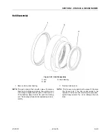
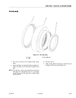
Страница 70: ...spindle bearings with multi pur pose grease MPG before assembly Do not overtighten spindle bearing nut Replace spindle seal if worn dam aged or leaking 1 Install the bearing with the flange surface on...

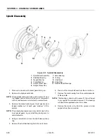
Страница 71: ...ll pins with a light coat of molypaste before assembly Pack inner and outer spindle bearings with multi pur pose grease MPG before assembly Do not overtighten spindle bearing nut Replace spindle seal...

Страница 72: ...four pins attaching the platform to the arm stack 4 Lift the platform from the arm stack and set aside NOTE When attaching platform back onto scissor arm assembly follow removal procedures in reverse...

Страница 73: ...SECTION 3 CHASSIS SCISSOR ARMS 3121273 JLG Lift 3 41 Figure 3 41 Arms and Platform Positioning and Support...

Страница 74: ...SECTION 3 CHASSIS SCISSOR ARMS 3 42 JLG Lift 3121273 Figure 3 42 1932RS 6RS Scissor Arm Assembly Ref Figure 3 43 A B I F C H C C E E D G...

Страница 75: ...SECTION 3 CHASSIS SCISSOR ARMS 3121273 JLG Lift 3 43 Figure 3 43 1932RS 6RS Scissor Arm Assembly Pin Configuration A A D F G C B E I H...

Страница 76: ...SECTION 3 CHASSIS SCISSOR ARMS 3 44 JLG Lift 3121273 Figure 3 44 3248RS 10RS Scissor Arm Assembly Ref Figure 3 45 A C D E E E E F F E E E H J E E E L E K K C G C C B B...

Страница 77: ...SECTION 3 CHASSIS SCISSOR ARMS 3121273 JLG Lift 3 45 Figure 3 45 3248RS 10RS Scissor Arm Assembly Pin Configuration A G E F H L J...

Страница 78: ...e harness on the machine Orange and yellow marker tape strips are located on the platform harness to assist in installation At every yellow marker tape secure the harness to the nuts welded on the arm...

Страница 79: ...Drive and Lift Select Switch 11 Low Battery Charge Sys tem Fault Indicator 10 01 13 23 62 B 1 3 4 8 9 10 2 5 1 2 6 7 11 Figure 3 49 Platform Control Station Components Internal 1 Drive and Lift Joyst...

Страница 80: ...tions InputVoltage 5 0 1 VDC CurrentConsumption 10mA 12VDC Output Handle Centered 2 5 0 1 VDC Output FullPositive Reverse Deflection 4 0 1 VDC Output FullNegative Forward Deflection 1 0 1 VDC Table 3...

Страница 81: ...oaded to center position therefore when the control is released the spool automatically returns to neutral pro hibiting any flow through the circuit Relief Valves Main relief valves are installed at v...

Страница 82: ...e Control System shall be energized in Ground Mode during testing For a convenient Ground Reference place the black meter lead on the negative post of the left battery in the left side batter compartm...

Страница 83: ...ted or mechanically frozen pump motor A clamp on ammeter set for 200A DC can be placed on either Pump Motor Cable for verification During Lift Up the ammeter will read approximately 150A Hydraulic Oil...

Страница 84: ...place the tank Torque mounting bolts to 6 7 ft lb 8 5 10 Nm d If only replacing the oil filter and maintenance is complete reinstall tank assembly on machine remove fill cap and refill tank with prope...

Страница 85: ...elief Valve 13 Steer Relief Valves 14 Valve Coil for Steer Cylinder 15 Gear Pump 16 Return Filter w Bypass 17 Return Filter Pipe 18 1 4 JIC BSPP Adapter 19 3 8 JIC BSPP 90 Adapter 20 Product ID Plate...

Страница 86: ...checked 2 Carefully disconnect hydraulic hoses from retract port of cylinder There will be some initial weeping of hydraulic fluid which can be caught in a suitable container After the initial dischar...

Страница 87: ...bles or hoses to the lift cylinder NOTICE DISCONNECT MAIN POWER FROM THE BATTERIES BEFORE REMOVING ANY COMPONENTS FROM THE LIFT CYLINDER ASSEMBLY 3 Remove the valve connector the two hoses and the man...

Страница 88: ...ith hammer in threaded area and try again Repeat if necessary until head is completely removed 7 Attach a suitable pulling device to the cylinder rod port block end or cylinder rod end as applicable N...

Страница 89: ...iston surface or replace piston as necessary 7 Inspect threaded portion of piston for damage Dress threads as necessary 8 Inspect seal and o ring grooves in piston for burrs and sharp edges Dress appl...

Страница 90: ...der head 4 Install washer ring onto rod carefully install the head gland on the rod ensuring that the wiper and rod seals are not damaged or dislodged Push the head along the rod to the rod end as app...

Страница 91: ...LING THE ROD OFF CENTER WHICH COULD CAUSE DAMAGE TO THE PISTON AND CYLINDER BARREL SURFACES 17 With the barrel clamped securely and while ade quately supporting the rod insert the piston end into the...

Страница 92: ...install the cartridge type holding valve and fittings in the port block using new o rings as applicable Refer to Figure 4 13 1932RS 6RS Lift Cylinder on page 4 13 or Figure 4 14 3248RS 10RS Lift Cylin...

Страница 93: ...lve 6 Extend Retract Block Fittings 7 Head 8 Seal 9 Seal w Backing Ring 10 O Rings 11 Wear Ring 12 Rod Piston 13 D Ring 14 Seal 15 Wear Ring 16 O Ring 17 Piston Nut 1 3 4 5 6 10 13 14 15 16 Torque 240...

Страница 94: ...ck Valve 6 Pressure Tank Block Fittings 7 Head 8 Seal 9 Seal w Backing Ring 10 O Rings 11 Wear Ring 12 Rod Piston 13 D Ring 14 Seal 15 Wear Ring 16 O Ring 17 Piston Nut 1 2 3 4 5 7 8 9 10 11 12 13 16...

Страница 95: ...Head 4 Wiper Seal 5 Rod Seal 6 Wear Ring 7 O Ring 8 O Ring 9 Piston 10 Rod O Ring 11 Piston Seal 12 Wear Ring 13 Nut 14 Hose Fittings 15 O Ring 1 2 3 4 5 6 7 8 10 11 12 13 14 9 Torque 97 119 ft lb To...

Страница 96: ...Head 4 Wiper Seal 5 Rod Seal 6 O Ring 7 Wear Ring 8 O Ring 9 Piston 10 Piston O Ring 11 Piston Seal 12 Wear Ring 13 Nut 14 Hose Fittings 15 O Ring 1 2 3 4 5 6 7 8 9 10 11 12 13 14 Torque 97 119 ft lb...

Страница 97: ...stic port and connect the remaining end of the cable to the analyzer NOTE The cable has a four pin connector at each end of the cable the cable cannot be connected back wards 2 Power up the Control Sy...

Страница 98: ...m mode HELP 001 EVERYTHING OK In ground mode HELP 002 GROUND MODE OK If ENTER is pressed again the display moves to the fol lowing display LOG 211 1 Power Cycle Or last recorded fault At this point th...

Страница 99: ...Press ENTER to select the ACCESS LEVEL menu Using the UP or DOWN arrow keys enter the first digit of the password 3 Then using the RIGHT arrow key position the cursor to the right one space to enter t...

Страница 100: ...adjust its value for example FAILURE TO MAKE THE PROPER SETTINGS FOR THE PARTICU LAR MACHINE CAN RESULT IN IMPROPER OPERATION GROUND ALARM 1 DESCENT The effect of the machine digit value is displayed...

Страница 101: ...Complete will appear Power down the machine Updating Software Updating the power control module software requires a laptop computer connecting cable and software update cd Contact JLG Industries to a...

Страница 102: ...SYSTEM 5 6 JLG Lift 3121273 Figure 5 3 Analyzer Menu Access Level JLG Analyzer Diagnos c Interface CALIBRATIONS EMULATION MODE MACHINE SETUP PERSONALITIES DIAGNOSTICS HELP PRESS ENTER SYSTEM TEST ACC...

Страница 103: ...ELEV SW2 OPEN CLOSED BATTERY XX XV STEER RIGHT OFF ON STEER LT OPEN CLOSED STEER RT OPEN CLOSED HORN OPEN CLOSED TRIGGER OPEN CLOSED JOYSTICK 100 to 100 FOOTSWITCH OPEN CLOSED Displayed when FOOTSWIT...

Страница 104: ...S ALRM Pla orm Mode Only TEST OVLD ALRM Ground Mode Only TEST PLT SW Pla orm Mode Only TEST GND SW Ground Mode Only TEST VALVES RUN SYSTEM TEST YES ENTER NO ESC FWD TO MAX SYS DISTRESS OVERLD LEFT LIF...

Страница 105: ...OUND ACCEL 0 1 5 0S STATIC 0 100 UP ACCEL 0 1 5 0S MAX CUR 0 100 FWD MIN 2 20 2 40V MAX CUR 0 100 OVR DBNCE 0 0 5 0S HORN 5 100 DECEL 0 1 1 0S DRIVE 0 100 UP DECEL 0 1 1 0S FWD MAX 1 00 1 50V FLD MAX...

Страница 106: ...HARGER INTERLOCK 0 DRIVE ONLY 1 DRV LIFT UP CHARGER INTERLOCK 0 DRIVE ONLY 1 DRV LIFT UP GROUND ALARM 0 HORN ONLY 1 DESCENT 2 MOTION GROUND ALARM 0 HORN ONLY 1 DESCENT 2 MOTION GROUND ALARM 0 HORN ONL...

Страница 107: ...TER NO ESC CAL JOYSTICK YES ENTER NO ESC MAX PUMP CUR CAL LOAD 110 LOAD CENTER NOM FIELD CURR CAL ANGLE LIFT TO MAX CAL JOYSTICK FWD TO MAX PUMP ADJ CAL JOYSTICK CENTER CAL JOYSTICK REV TO MAX CAL JOY...

Страница 108: ...5 12 JLG Lift 3121273 Figure 5 9 Analyzer Menu Emulation Mode JLG Analyzer Diagnos c Interface CALIBRATIONS EMULATION MODE MACHINE SETUP PERSONALITIES DIAGNOSTICS HELP PRESS ENTER SYSTEM TEST ACCESS...

Страница 109: ...LIFT UPACCEL 0 1 5 0 Sec 0 5 0 5 0 5 0 5 UPDECEL 0 1 1 0 Sec 0 1 0 1 0 1 0 1 DN ACCEL 0 1 5 0 Sec 0 1 0 1 0 1 0 1 DNDECEL 0 1 5 0 Sec 0 1 0 1 0 1 0 1 UPMIN 0 50 20 20 20 20 UPMAX 0 100 100 100 100 10...

Страница 110: ...TERLOCK 0 1 DRIVEONLY Drivemotionpreventedwhilevehicleischarging DRIVEANDLIFTUP Driveandliftupmotionsarepreventedwhilevehicleischarg ing RequiredforCE 0 5 GROUND ALARM 0 1 2 NOTINSTALLED Vehiclealarmw...

Страница 111: ...S DTC The DTC tables following are sorted in groups by the first two digits these digits represent the number of flashes the system distress indicator lamp will flash on the platform indicator panel w...

Страница 112: ...EM TRIGGER PERMANENTLY CLOSED 6 6 2210 TRIGGER CLOSED TOO LONG WHILE IN NEUTRAL 6 6 2232 FUNCTION PROBLEM DRIVE LIFT BOTH OPEN 6 6 2 3 Ground Controls 6 7 231 FUNCTION PROBLEM LIFT PERMANENTLY SELECTE...

Страница 113: ...4 2 Thermal Limit SOA 6 12 421 POWER MODULE TOO HOT PLEASE WAIT 6 12 422 DRIVING AT CUTBACK POWER MODULE CURRENT LIMIT 6 12 423 LIFT UP AT CUTBACK POWER MODULE CURRENT LIMIT 6 12 4 4 Battery Supply 6...

Страница 114: ...9952 POWER MODULE FAILURE INTERNAL ERROR 6 15 9953 POWER MODULE FAILURE INTERNAL ERROR 6 15 9954 POWER MODULE FAILURE INTERNAL ERROR 6 15 9955 POWER MODULE FAILURE INTERNAL ERROR 6 15 9956 POWER MODUL...

Страница 115: ...t 24 volts Backprobing ground board J1 19 should show about 0 volts HEALTH Status LED ON 005 DRIVE LIFTUPPREVENTED TILTED ELEVATED Drivingis not possible sincetheplat formiselevated and thechassisis n...

Страница 116: ...CHES FAULTY Boththe Steer Left and Steer Right Inputsare closed asthe sametime Check if the steer switches are damaged obstructed or jammed A short in the Steer Switch wiring or a failed Steer Switch...

Страница 117: ...ake release switch input 24V is from ground board terminal J1 31 and its output 24V when closed is to ground board terminal J1 25 If the brakes are released the machine can be pushed or moved without...

Страница 118: ...heModelSelection usingtheJLGAnalyzer Check ANALYZER MACHINE SETUP MODEL NUMBER Cycle Emergency Stop Switch Replace ground board HEALTH Status LED ON 2510 DRIVEPREVENTED BRAKES NOTRELEASING While drivi...

Страница 119: ...tatus LED ON 3 3 Ground Output Driver DTC FAULT MESSAGE DESCRIPTION CHECK 333 LIFTUPVALVE SHORTTO BATTERY Voltage fromanexternal source was detected on theLiftUpSolenoid J2 17 NUV Check for continuity...

Страница 120: ...ected on theSteerLeftSolenoid J2 18NRV Check for continuity through this circuit Steer right solenoid resistance should measure about 30 Ohms The steer right sole noid is powered with 24V from ground...

Страница 121: ...r left solenoid detected J2 9 NLV HEALTH Status LED ON 33299 LINECONTACTOR COIL SHORTTOBATTERY Voltage fromanexternal source was detected on theNegativeMain Line Contactor HEALTH Status LED ON 33302 N...

Страница 122: ...rrent consumption in the pump ANALYZER DIAGNOSTICS PUMP PUMP CUR over 130 Amps with an empty deck Refer to Section 4 3 Pump Motor HEALTH Status LED ON 4 4 Battery Supply DTC FAULT MESSAGE DESCRIPTION...

Страница 123: ...e pump and trac tion has not increased more than 1 3V in 1000mS Alternately the VMN of the pump or traction is less than 20 of battery volt age If this message persists after disconnecting the drive a...

Страница 124: ...er sists after a power cycle it may be an internal issue HEALTH Status LED ON 8 2 LSS Load Sensing System See 3124288 LSS Manual DTC FAULT MESSAGE DESCRIPTION CHECK 8212 LSSPRESSURESENSOR DISAGREEMENT...

Страница 125: ...TINGS Thecontrolsystemdetected an EEPROMfailure Personalities and Machine Setup settings may be reset to default values Check Correct all settings and re cycle power to clear dif ficulty Health Status...

Страница 126: ...ntRAMinforma tionstoredin theinterfacePCB Cycle machine if error still exists replace System Module HEALTH Status LED ON 9971 POWERMODULEFAILURE INTERNAL ERROR Cycle machine if error still exists repl...

Страница 127: ...age source Backprobing To backprobe means to take the measurement by accessing a connector s contact on the same side as the wires the back of the connector Readings can be done while maintaining circ...

Страница 128: ...orrect range See multimeter s operation manual Use firm contact with meter leads First test meter and leads by touching leads together Resistance should read a short circuit very low resis tance Circu...

Страница 129: ...F before testing con tinuity Disconnect component from circuit before testing Use firm contact with meter leads First test meter and leads by touching leads together Meter should produce an audible al...

Страница 130: ...wire under test or are within reach of the jumper 1 Disconnect all connections associated with the wire under test and the two additional wires If harness is not com pletely isolated disconnect batte...

Страница 131: ...evel conductivity silicone dielectric grease must be packed completely around male and female pins on the inside of the connector after the mating of the housing to the header This is easily achieved...

Страница 132: ...ee Figure 7 7 Connector Assembly 2 of 4 2 Pull back on the contact wire with a force of 1 or 2 lb to be sure the retention fingers are holding the contact See Fig ure 7 7 Connector Assembly 2 of 4 3 A...

Страница 133: ...nnector Assembly 4 of 4 Disassembly 5 Insert a 4 8 mm 3 16 wide screwdriver blade between the mating seal and one of the red wedge lock tabs 6 Pry open the wedge lock to the open position 7 While rota...

Страница 134: ...e wedge lock should never be removed from the housing for insertion or removal of the contacts Wedge Lock The wedge lock has slotted openings in the forward or mating end These slots accommodate circu...

Страница 135: ...probe wires by piercing the insulation with a sharp point This practice should be discouraged when dealing with the AMPSEAL plug assembly or any other sealed connector system The resulting pinholes i...

Страница 136: ...he wed gelock will snap into place Rectangular wedges are not oriented Thy may go in either way NOTE The receptacle is shown use the same procedure for plug DT DTP Series Disassembly Figure 7 13 DT DT...

Страница 137: ...For unused wire cavities insert sealing plugs for full environmental sealing HD30 HDP20 Series Disassembly Figure 7 16 HD HDP Contact Removal 11 With rear insert toward you snap appropriate size extra...

Страница 138: ...it switches are used to control movement or indicate position Mechanical limit switches are just like manually oper ated switches except that the moving object operates the switch These switches can b...

Страница 139: ...positive side of the power source and the load This switch is called a high side switch The switch supplies the power to the load When a switch is wired between the negative side of the power source a...

Страница 140: ...Sensing Digital Input 15 SpareDigitalInput High Sensing Digital Input 16 Spare 5V Power Output 17 Spare Negative Power Output 18 ElevationSwitch SW2 Connectto BATT Power Output 19 ElevationSwitch SW1...

Страница 141: ...Mode Power Input 9 NegativeSteerLeftSolenoid Valve Low SideDriver Digital Output 10 Joystick Trigger Pin 2 Digital Input 11 PlatformHornSwitch Digital Input 12 Joystick SteerRight Digital Input 13 Dri...

Страница 142: ...WHT 24 TX WHT 23 RX WHT 23 RX WHT 21 12V IGN WHT 21 12V IGN TILT SENSOR SN31 1 2 3 S33 S34 S36 ELEVATION SN37 1 2 3 4 BEACON LB44 1 2 X45 1 WHT 6 P MAIN CON WHT 6 2 IGN RELAY WHT 7 N MAIN CON WHT 7 2...

Страница 143: ...15 ST RIGHT VLV WHT 15 ST RIGHT VLV WHT 18 CHARGING STAT GING STAT IFT UP SW L 3 1 3 IGN 9 R BRAKE WHT 9 R BRAKE 8 L BRAKE WHT 8 L BRAKE YEL 3 1 2 R BRK IGN R BRK IGN YEL 3 1 1 L BRK IGN L BRK IGN WHT...

Страница 144: ...1 A1 1 MS01 F 1 2 MS02 B 1 2 MS02 A2 1 MS02 A1 1 MS02 F 1 2 BLK RED 18AWG TFFN BRN BLK 18AWG TFFN BLU RED 18AWG TFFN YEL 18AWG TFFN BLU BLK 18AWG TFFN BRN 18AWG TFFN YEL BLK 18AWG TFFN RED 18AWG TFFN...

Страница 145: ...2 1 JOYSTICK JS47 1 2 3 4 5 6 7 8 9 WG TFFN BLK RED 18AWG TFFN WG TFFN BRN BLK 18AWG TFFN AWG TFFN BLU RED 18AWG TFFN TFFN YEL 18AWG TFFN WG TFFN BLU BLK 18AWG TFFN TFFN BRN 18AWG TFFN WG TFFN YEL BLK...

Страница 146: ...21273 Figure 7 19 Electrical Components Layout Sheet 1 of 2 GROUND CONTROL PANEL PLATFORM RECEPTACLE PLATFORM CONTROL BOX LSS LIFT CYLINDER TRANSDUCERS RELAY BRAKE RELEASE LIFT CYLINDER VALVE BLOCK TI...

Страница 147: ...t 7 21 Figure 7 19 Electrical Layout Sheet 2 of 2 ALARM BEACON LIGHT REAR BEACON LIGHT FRONT BATTERIES LEFT DRIVE MOTOR RIGHT DRIVE MOTOR DRIVE MODULE BF1 BF2 B J1 F1 J2 F2 B T P CONTACTOR RELAY PUMP...

Страница 148: ...SECTION 7 GENERAL ELECTRICAL INFORMATION SCHEMATICS 7 22 JLG Lift 3121273 7 8 HYDRAULIC SCHEMATIC Hydraulic Schematic 2792599C Figure 7 20 Hydraulic Schematic 1001131095_E...

Страница 149: ...ORNIANPROPOSITION65 BATTERYWARNING Batteryposts terminalsandrelated accessoriescontain leadandleadcompounds chemical knowntothe Stateof Califormia tocausecancer and reproductiveharm WASHHANDS AFTERHAN...

Страница 150: ...erhude Ihlpohl Germany 49 0 421 69350 0 49 0 421 69350 45 Email german parts jlg com JLG Equipment Services Ltd Rm 1107 Landmark North 39 Lung Sum Avenue Sheung Shui N T Hong Kong 852 2639 5783 852 26...

Отзывы: