SECTION 4 - HYDRAULICS
3121273
– JLG Lift –
4-7
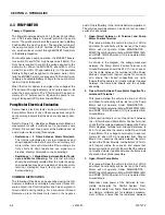
4.6 LIFT CYLINDER REMOVAL
NOTE:
If there is a pump failure, a crane or a forktruck can be used
to raise the platform. Refer to Figure 3.15, Scissor Arms
Removal.
Self locking fasteners, such as nylon insert and thread
deforming locknuts, are not intended to be reinstalled
after removal. Always use new replacement hardware
when installing locking fasteners.
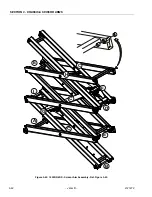
1. Raise the platform and use an overhead crane or
fork truck to secure the platform and scissor arms
before lift cylinder removal begins. (See Figure 3-
41.)
2. Cut any wire ties that attach any cables or hoses to
the lift cylinder.
NOTICE
DISCONNECT MAIN POWER FROM THE BATTERIES BEFORE
REMOVING ANY COMPONENTS FROM THE LIFT CYLINDER
ASSEMBLY.
3. Remove the valve connector, the two hoses and the
manual decent cable from the cylinder.
NOTE:
To avoid having to readjust the manual descent, remove the
large nut located behind the manual descent bracket as
shown.
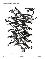
Also see Figures 3-42., 3-43., 3-44., for lift cylinder mount-
ing hardware configurations.
4. Ensuring that the deck and scissor arms are prop-
erly secure, remove the top lift cylinder pin and rest
the top of the cylinder on the arm cross tube directly
below the cylinder.
5. Remove the bolt from the lower cylinder pin and
have someone assist you in lifting the cylinder from
the scissor arms.
6. Place the cylinder on a clean workbench.
Содержание 1932RS
Страница 1: ...Service Maintenance Manual Models 1932RS 6RS 3248RS 10RS 3121273 April 8 2013...
Страница 2: ......
Страница 12: ...viii JLG Lift 3121273 TABLE OF CONTENTS NOTES...
Страница 69: ...SECTION 3 CHASSIS SCISSOR ARMS 3121273 JLG Lift 3 37 NOTES...
Страница 73: ...SECTION 3 CHASSIS SCISSOR ARMS 3121273 JLG Lift 3 41 Figure 3 41 Arms and Platform Positioning and Support...


