SECTION 6 - DIAGNOSTIC TROUBLE CODES
3121273
– JLG Lift –
6-1
SECTION 6. DIAGNOSTIC TROUBLE CODES
6.1 INTRODUCTION
This section provides a reference for Diagnostic Trouble Codes (DTC) read from the Multifunction Digital Indicator (MDI) or a
handheld analyzer. For more information on any sensors or indicators, refer to the appropriate manual section. Many of the
checks below require configuring and using a multimeter. Refer to Section 7: General Electrical Information & Schematics for
multimeter basics. To troubleshoot multiple DTCs, start with the DTC with the higher first two digits. The machine is powered
by four 6 Volt batteries in series, providing a nominal 24 Volts to the control system. Some procedures below refer to this
nominal voltage (VMN) as 24V. Actual voltage measurements may differ based on the charge of the batteries.
If a correction
is made during a check, conclude the check by cycling the machine power, using the emergency stop switch.
It may
also be helpful to run a system test, ANALYZER -> SYSTEM TEST for intermittent or difficult problems.
System Fault/DTC Indication
In addition to the DTC codes being displayed on the MDI and handheld analyzer, DTC codes are indicated by the number of
flashes and pauses of the Low Battery Charge/System Fault indicator on the face of the platform control box as shown below:
6.2 DIAGNOSTIC TROUBLE CODES (DTC)
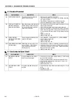
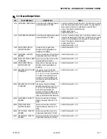
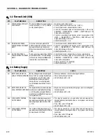
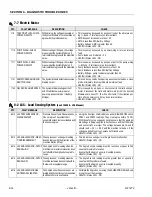
The DTC tables following are sorted in groups by the first two digits, these digits represent the number of flashes the system
distress indicator lamp will flash on the platform indicator panel when a fault occurs.
For example: a “2-1 Power-Up” on page 6-5 would be indicated by 2 flashes, a pause, then 1 flash, a pause, then would
keep repeating until the fault is cleared.
The more detailed three digit code numbers in the DTC column of the following tables are only indicated on a JLG handheld
diagnostic analyzer.
To troubleshoot multiple DTCs, start with the DTC with the higher first two digits.
If a correction is made during a check,
conclude the check by cycling the machine power off then back on, using the emergency stop switch.
NOTE:
Reference to the Health (Status LED) indicator is the LED indicator on the system power module itself. (See “ZAPI
Power Module Electrical Evaluation” on page 3-18.)
6.3 X-CONNECTOR REFERENCES
Throughout the following DTC troubleshooting procedures, electrical connectors are given a three digit identifier number
preceded with an “X” for identifying and locating the specific connector on the machine.
See Section 9.8, X-CONNECTOR ID INDEX for description of "X" connectors and Figure 9-12. on page 9-20, and Figure 9-13.
on page 9-21 for location of "X" connectors on the machine.
Example of "X" connector usage nomenclature:
[X006.21] refers to terminal 21 (pin and socket) of connector X006.
[X006.21.soc] refers to the socket side of terminal 21, connector X006.
[X006.21.pin] refers to the pin side of terminal 21, connector X006.
1
2
Содержание 1932RS
Страница 1: ...Service Maintenance Manual Models 1932RS 6RS 3248RS 10RS 3121273 April 8 2013...
Страница 2: ......
Страница 12: ...viii JLG Lift 3121273 TABLE OF CONTENTS NOTES...
Страница 69: ...SECTION 3 CHASSIS SCISSOR ARMS 3121273 JLG Lift 3 37 NOTES...
Страница 73: ...SECTION 3 CHASSIS SCISSOR ARMS 3121273 JLG Lift 3 41 Figure 3 41 Arms and Platform Positioning and Support...


