SECTION 6 - DIAGNOSTIC TROUBLE CODES
6-8
– JLG Lift –
3121273
255
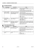
PLATFORM OVERLOADED
The load sensing system measured
platform load is excessive.
• Remove excess weight from the platform.
• Check that the platform is not caught on something, preventing
up or down movement.
• If any CAN bus faults are active, troubleshoot those first.
• Refer to Troubleshooting in the LSS manual, 3124288.
258
DRIVE & LIFT PREVENTED -
BRAKES ELECTRICALLY
RELEASED FOR TOWING
Manual brake release mode is activated
with the switch under the left side chas-
sis cover near the ground control box.
Drive or lift is not possible.
• Push manual brake release switch again or cycle power to clear
manual brake release mode.
• Check if the brake release switch is obstructed or jammed.
• Check the brake release switch signal and wiring to the ground
board. The switch input (24V) is from ground board terminal J1-
31, and its output (24V when closed) is to ground board terminal
J1-25.
• Replace ground board.
• HEALTH (Status LED) - ON
259
MODEL CHANGED -
HYDRAULICS SUSPENDED -
CYCLE EMS
The user changed the Model Selection
using the JLG Analyzer.
• Check ANALYZER -> MACHINE SETUP -> MODEL NUMBER.
• Cycle Emergency Stop Switch.
• Replace ground board.
• HEALTH (Status LED) - ON
2510
DRIVE PREVENTED - BRAKES
NOT RELEASING
While driving on a level surface, arma-
ture current was > 150A for five sec-
onds. Brakes assumed to not be
releasing properly.
• Ensure vehicle is not stuck on something preventing movement.
• Examine both drive motor brakes for electrical (open- and short-
circuits) and mechanical (rust, corrosion, contamination) issues
that prevent them from releasing.
• HEALTH (Status LED) - ON
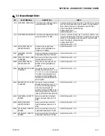
3-1 Line Contactor Open Circuit
DTC
FAULT MESSAGE
DESCRIPTION
CHECK
311
OPEN CIRCUIT LINE CON-
TACTOR
The System Module's Line Contactor
did not close when energized.
• Check contactor main contact wiring to battery (+) terminal and
power controller terminal B+.
• Contactor solenoid resistance should measure about 52 Ohms.
• Check contactor solenoid wiring to terminals J1-13 and J1-32.
• Replace the line contactor.
• HEALTH (Status LED) - ON
314
AUXILIARY RELAY - OPEN
CIRCUIT
The auxiliary relay did not close when
energized.
• Check the auxiliary relay coil and associated wiring to J1-13 and
J1-32.
• No voltage on J1-28.
• HEALTH (Status LED) - ON
2-5 Function Prevented
DTC
FAULT MESSAGE
DESCRIPTION
CHECK
Содержание 1932RS
Страница 1: ...Service Maintenance Manual Models 1932RS 6RS 3248RS 10RS 3121273 April 8 2013...
Страница 2: ......
Страница 12: ...viii JLG Lift 3121273 TABLE OF CONTENTS NOTES...
Страница 69: ...SECTION 3 CHASSIS SCISSOR ARMS 3121273 JLG Lift 3 37 NOTES...
Страница 73: ...SECTION 3 CHASSIS SCISSOR ARMS 3121273 JLG Lift 3 41 Figure 3 41 Arms and Platform Positioning and Support...


