SECTION 6 - DIAGNOSTIC TROUBLE CODES
6-14
– JLG Lift –
3121273
779
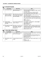
TRACTION T LOW - CHECK
POWER CIRCUITS
While driving, the voltage measured at
the System Module’s T terminal did not
agree with the predicted value.
• This issue may be caused by an opencircuit of the armature wir-
ing (+B and –T terminals) or an internal fault.
• VMN does not increase more than 1.3V
• VMN is less than 20% Battery Voltage
• Battery Voltage . VMN is greater than 4V
• HEALTH (Status LED) - ON
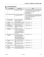
7710
PUMP P HIGH - CHECK
POWER CIRCUITS
While steering or lifting up, the voltage
measured at the System Module’s P
terminal did not agree with the predicted
value.
• This issue may be caused by a power wiring error or an internal
fault.
• Pump Feedback . Predicted >7V
• HEALTH (Status LED) - ON
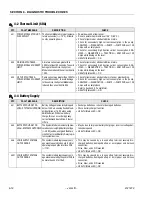
7711
PUMP P LOW - CHECK
POWER CIRCUITS
While steering or lifting up, the voltage
measured at the System Module’s P
terminal did not agree with the predicted
value.
• This issue may be caused by an open-circuit of the pump wiring
(+BF2 and –P terminals) or an internal fault.
• Pump feedback does not increase more than 1.3V
• Pump feedback is less than 20% Battery Voltage
• Battery Voltage - pump feedback is greater than 4V
• HEALTH (Status LED) - ON
7741
ARMATURE BRAKING CUR-
RENT TOO HIGH
The System Module detected excessive
braking current.
• This can be caused by transporting an excessive load on a steep
grade. Alternately, this may indicate an internal fault.
• HEALTH (Status LED) - ON
7742
FIELD VOLTAGE IMPROPER The System Module voltage at the F1
and F2 terminals was improper at
power-up (expected to be ½ Battery
Voltage).
• This is caused by an open- or short-circuit in the field wiring or
motor. Disconnect the field and motor wiring from the System
Module and connect F1 / F2 with a short wire. If the situation per-
sists after a power cycle, it may be an internal issue.
• HEALTH (Status LED) - ON
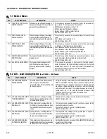
8-2 LSS - Load Sensing System
(See 3124288 - LSS Manual)
DTC
FAULT MESSAGE
DESCRIPTION
CHECK
8212
LSS PRESSURE SENSOR -
DISAGREEMENT
Pressure Sensor 1 and Pressure Sensor
2 do not agree. The system shall
assume the machine is overloaded until
the sensors agree.
• Using the Analyzer LOAD submenu under DIAGNOSTICS check
PRES1 and PRES2 readings. They must agree within 75 PSI.
With the safety prop engaged check to ensure that the appropri-
ate voltage is being supplied to both sensors and that the wiring
and connections are intact. The voltage between pins A and B
should read +5V +/- 0.5V with the machine turned on. If the
voltage supplied is correct, replace both transducers.
• HEALTH (Status LED) - ON
8213
LSS ANGLE SENSOR - DIREC-
TION DISAGREEMENT
The angle sensor’s change in reading
does not agree with the direction of the-
machine motion (lift up).
• This indicates a wiring error or Angle Sensor malfunction.
• HEALTH (Status LED) - ON
8214
LSS ANGLE SENSOR - OUT OF
RANGE HIGH
The Angle Sensor's reading when the
machine is at maximum elevation does
not fall within the high end acceptable
range
• The Angle Sensors reading must be less than or equal to 245
counts at maximum elevation.
Ensure that the Angle Sensor is mounted properly.
• HEALTH (Status LED) - ON
8215
LSS ANGLE SENSOR - OUT OF
RANGE LOW
The angle sensor’s reading when the
machine is stowed does not fall within
the low end acceptable range.
• The Angle Sensors reading must be greater than or equal to 5
counts with the platform stowed.
Ensure that the Angle Sensor is mounted properly.
• HEALTH (Status LED) - ON
8216
LSS ANGLE SENSOR HAS
NOT BEEN CALIBRATED
The Angle Sensor has never been cali-
brated and the control system assumes
that the platform is overloaded.
• Calibrate the Angle Sensor using the CALIBRATION: ANGLE sub-
menu to clear the message.
• HEALTH (Status LED) - ON
7-7 Electric Motor
DTC
FAULT MESSAGE
DESCRIPTION
CHECK
Содержание 1932RS
Страница 1: ...Service Maintenance Manual Models 1932RS 6RS 3248RS 10RS 3121273 April 8 2013...
Страница 2: ......
Страница 12: ...viii JLG Lift 3121273 TABLE OF CONTENTS NOTES...
Страница 69: ...SECTION 3 CHASSIS SCISSOR ARMS 3121273 JLG Lift 3 37 NOTES...
Страница 73: ...SECTION 3 CHASSIS SCISSOR ARMS 3121273 JLG Lift 3 41 Figure 3 41 Arms and Platform Positioning and Support...


