24
5.2 Wheel balancing
Balancing of every wheel consists in determining the volume of imbalance expressed in grams
for inner and outer correction plane and localising position of imbalance on the wheel. In order to
clearly identify the volume of imbalance, it is necessary to enter the following data into the
machine memory: WIDTH, DIAMETER, DISTANCE
— corresponding to geometrical dimensions
of the wheel to be balanced, select balancing programme (manner and positions of correction
weights) and enter the value of the cut-off threshold.
CAUTION
If one wants to balance the wheel whose parameters were previously saved in the memory
M
of
the computer, then it is enough to press button
M
to enter data on this wheel.
Upon entering the measuring setpoints, the wheel should be brought up to speed of at least 95
rpm. The measuring cycle is conducted with no interference on the side of the operator and is
completed by displaying the value of imbalance in the indicator screen.
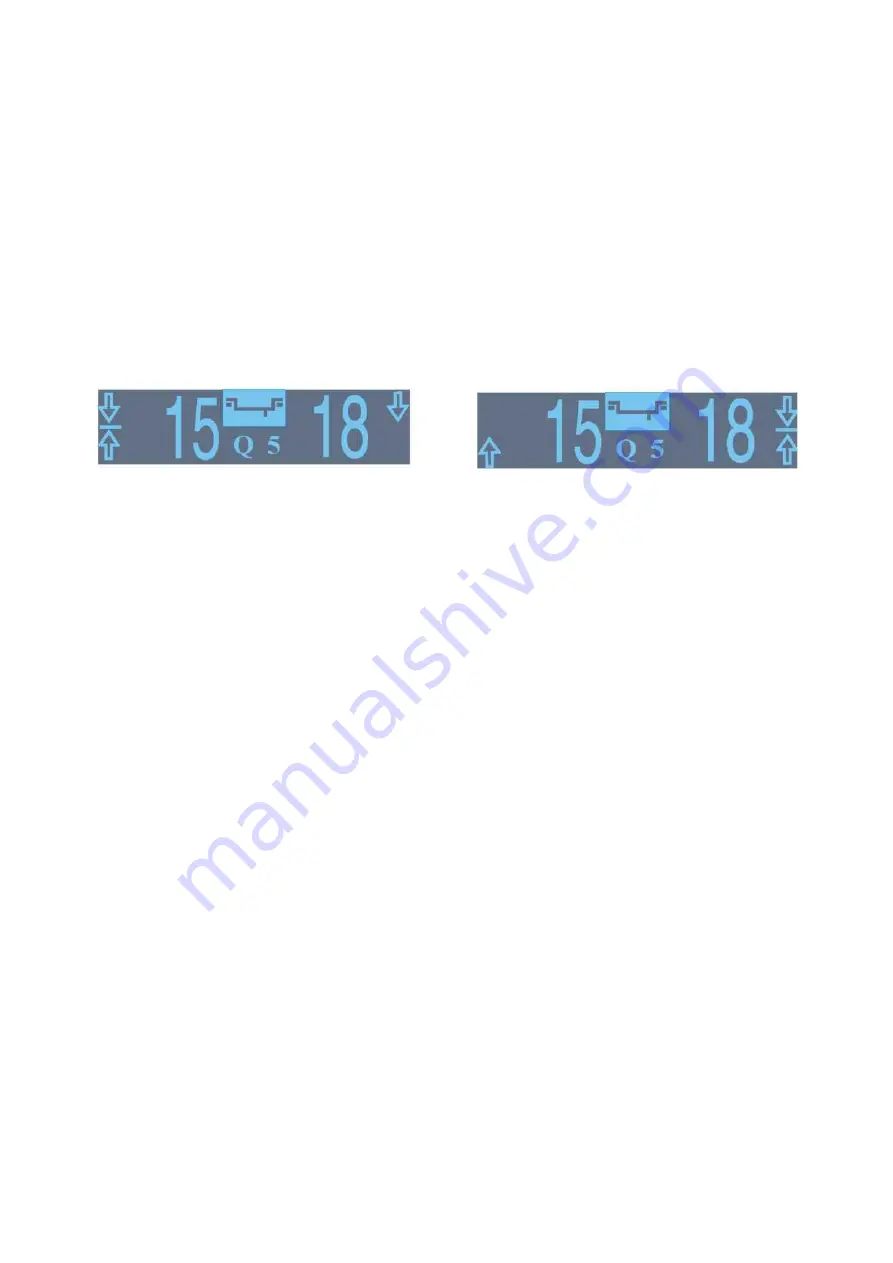
The indicator screen displayed exemplary values of imbalance:
- 15 g
— applicable to inner left correction plane
- 18 g
— applicable to outer right correction plane
spinning the wheel slowly, at each revolution one may hear sound signals slightly different from
one another.
They occur in such wheel positions for which the arrows defining the position of imbalance are
directed towards one another.
The value of 15 g displayed in the indicator screen means that the weight of 15 g should be
attached on the inner edge of the rim in order to balance the imbalance. Watch the arrows while
spinning the wheel in any direction. The sound signal shall be heard and arrows directed towards
one another only for one position of the wheel against any reference point. For this wheel
position, the weight of 15 g should be attached at the topmost point on the inner edge of the rim.
The position of attaching weight of 18 g (20 g) on the outer correction plane shall be searched in
the
same
manner.


