background image

62

07610-003-61-42-T

PARTS

DOOR INTERLOCK, EXHAUST FAN, TRANSFORMER BOX

DOOR INTERLOCK (SDI) /EXHAUST FAN CONTROL/TRANSFORMER MOUNTING BOX 

Door Interlock Box Bottom

05700-001-21-26

Door Interlock Box Cover

05700-001-21-27

DESCRIPTION

PART NUMBER

Pipe Clamp (found on the side of the machine)

05700-000-35-05

Solenoid, Electrical Interlock Option

04810-100-61-33

Relay

05945-111-47-51

OTHER DOOR INTERLOCK (SDI) COMPONENTS (NOT SHOWN):

Transformer Mounting Bracket

05700-031-62-82

Exhaust Fan Control

2” Din Rail

05700-002-36-09

415/440/460V Transformer

05950-111-65-93

380V Transformer

05950-111-64-17

Exhaust Fan Control

Delay Timer

05945-011-65-44

Transformer Mounting Box

05700-002-10-01

Transformer Mounting Box Top 

(not shown)

05700-000-78-53

2 Amp Circuit Breaker

05925-111-64-18

Содержание TEMPSTAR

Страница 1: ...DEL S TEMPSTAR TEMPSTAR LT TEMPSTAR NB TEMPSTAR WITH VENTLESS AND ENERGY RECOVERY STEAM HEATED MODELS TEMPSTAR S TEMPSTAR LT NB VENTLESS S Technical Manual Rev T P N 7610 003 61 42 Issued 11 11 2008 Revised 01 11 16 TEMPSTAR SERIES UPRIGHT DOOR DISHMACHINES ...

Страница 2: ......

Страница 3: ...s improper installation if serial number has been removed or altered or if unit is used for a purpose other than originally intended TRAVEL LIMITATIONS Jackson WWS limits warranty travel time to 2 two hours and mileage to 100 one hundred miles Jackson WWS will not pay for travel time and mileage that exceeds this or any additonal fees such as those for air or boat travel without prior authorizatio...

Страница 4: ... pg 4 36 38 Paragraph content was changed on pg 7 Changes the PSI flow on pg 15 M 03 02 15 KAP QOF 386 Updated wire colors on schematic pg s 49 50 51 52 53 N 04 06 15 KAP N A Inserted note pertaining to corner installation pg 5 P 05 08 15 KAP N A Added Ventless Operating Capacities on pg 2 Added Pressure Regulator Option Dimensions on pg 5 Added Ventless Machine Dimensions on pg 6 Added Ventless p...

Страница 5: ...nical support toll free at 1 888 800 5672 Technical support is available for service personnel only TEMPSTAR Electrically heated high temp hot water sanitizing with booster heater door type dishmachine TEMPSTAR LT Electrically heated low temp chemical sanitizing no rinse booster door type dishmachine TEMPSTAR NB Electrically heated high temp hot water sanitizing no rinse booster door type dishmach...

Страница 6: ...bly Universal Timer 22 Hood Assembly Bolted Single Support Design 27 Cantilever Arm Door Assemblies 28 Tub Assembly 31 Steam Tub Assembly 34 Frame Assembly 37 Rinse Tank Assembly 38 Coil Assembly 40 Incoming Steam Plumbing Assembly 41 Wash Motors 43 Motor Pump Assembly 44 Wash Heaters Rinse Heaters 45 Incoming Outlet Plumbing Assembly 47 Tempstar Ventless Plumbing 53 1 2 Solenoid Valve 1 2 NPT Vac...

Страница 7: ...ar UT w Cycle Switches 460V 60 Hz three phase 70 Solid State Tempstar LT NB 208 230V 50 60 Hz single three phase 71 Tempstar LT NB 208 230V 50 60 Hz single three phase 72 Tempstar LT NB UT w Cycle Switches 460V 60 Hz three phase 73 Tempstar S Universal Timer 208 230V 60 Hz single three phase 74 SCHEMATIC OPTIONS SDI Options 75 Drain Quench Options 76 ADDENDUM Jackson Technical Manual Addendum 77 ...

Страница 8: ...03 61 42 T 1 LEGEND A WATER INLET 1 2 NPT B ELECTRICAL CONNECTION POINT C DRAIN 1 1 2 NPT D STANDARD CLEARANCE BETWEEN MACHINE AND WALL WITH DISH TABLE IS 4 10 2 cm SPECIFICATIONS Y STRAINER MACHINE DIMENSIONS ...

Страница 9: ...m DRAIN TO FLOOR 64 3 8 163 5 cm 60 5 8 154 cm 61 3 4 156 8 cm WATER INLET TO FLOOR C 15 1 2 39 4 cm 4 7 8 12 4 cm B D D A B PRESSURE REGULATOR MACHINE DIMENSIONS LEGEND A WATER INLET 1 2 NPT B ELECTRICAL CONNECTION POINT C DRAIN 1 1 2 NPT D STANDARD CLEARANCE BETWEEN MACHINE AND WALL WITH DISH TABLE IS 4 10 2 cm SPECIFICATIONS 2 ...

Страница 10: ... 2083mm 17 432mm 77 1956mm 131 4 335mm 43 4 120mm 3 79mm 151 2 394mm 4 60 1527mm C A B C A LEGEND A DRAIN 1 1 2 IPS B WATER INLET 3 4 MIP C ELECTRICAL CONNECTIONS ALL VERTICAL DIMENSIONS ARE 1 2 DUE TO ADJUSTABLE BULLET FEET 51 4 134mm 41 2 114mm 51 4 134mm 251 4 642mm 251 4 641mm 32 813mm B ...

Страница 11: ...81 cm ROLL TABLE DIMENSIONS CONNECTION TO DISHMACHINE TABLE DIMENSIONS CORNER INSTALLATION 4 10 2 cm MINIMUM 2 1 2 6 4 cm 25 1 4 64 1 cm 20 1 2 52 1 cm OPENING 25 1 4 64 1 cm TABLE DIMENSIONS STRAIGHT THROUGH INSTALLATION NOTE Please remove the front dress panel from the dishmachine if mounting dishmachine for a corner installation and attaching side tables Corner installation will trap panel maki...

Страница 12: ...sh Temperature Minimum F 150 Wash Temperature Minimum C 66 Rinse Temperature Minimum F 180 Rinse Temperature Minimum C 83 Inlet Water Temperature 12KW Rinse Heater F 140 12KW Rinse Heater C 60 14KW Rinse Heater F 110 14KW Rinse Heater C 44 Ventless F 40 70 Ventless C 4 4 21 Flow Pressure PSI 10 Water Line Size NPT Vented 1 2 Water Linse Sze Ventless 3 4 Drain Line Size NPT 1 1 2 TEMPSTAR LT Wash T...

Страница 13: ...08 1 50 12KW 240V 71 A 90 AMP 208 1 50 14KW 240V 78 A 100 AMP 230 1 50 12KW 240V 78 A 100 AMP 230 1 50 14KW 240V 86 A 110 AMP TEMPSTAR Electrical Characteristics 208 3 50 12KW 240V 45 A 60 AMP 208 3 50 14KW 240V 49 A 70 AMP 230 3 50 12KW 240V 48 A 60 AMP 230 3 50 14KW 240V 53 A 70 AMP 380 3 50 12KW 380V 29A 40 AMP 380 3 50 14KW 208V 34A 45 AMP 415 3 50 12KW 415V 26 A 35 AMP 415 3 50 14KW 415V 29 A...

Страница 14: ... A 21 A 30 AMP 380 3 50 N A 10 A 15 AMP 415 3 50 N A 10 A 15 AMP 440 3 50 N A 8 A 15 AMP 208 1 60 N A 26 A 35 AMP 230 1 60 N A 28 A 35 AMP 208 1 60 N A 26 A 35 AMP 230 1 60 N A 28 A 35 AMP 208 3 60 N A 18 A 25 AMP 230 3 60 N A 28 A 35 AMP 460 3 60 N A 8 A 15 AMP TEMPSTAR S Electrical Characteristics VOLTS PHASE HZ RINSE HEATER RATINGS TOTAL AMPS TYPICAL ELECTRICAL CIRCUIT 208 1 60 N A 6 A 15 AMP 2...

Страница 15: ...table bullet feet which can be turned using a pair of channel locks or by hand if the unit can be raised safely Ensure that the unit is level from side to side and from front to back before making any connections All plumbing connections must comply with all applicable local state and national plumbing codes The plumber is responsible for ensuring that the incoming water line is thoroughly flushed...

Страница 16: ...essure Static pressure is the line pressure in a no flow condition all valves and services are closed Flow pressure is the pressure in the fill line when the fill valve is opened during the cycle It is also recommended that a shock absorber not supplied with the Tempstar model be installed in the incoming water line This prevents line hammer hydraulic shock induced by the solenoid valve as it oper...

Страница 17: ...rounding lug Install the service wires L1 L2 and L3 3 phase only to the appropriate terminals as they are marked on the terminal block Install the grounding wire into the lug provided Tighten the connections It is recommended that DE OX or another similar anti oxidation agent be used on all power connections Ensure that the power switch is in the OFF position and apply power to the dishmachine Che...

Страница 18: ...11 07610 003 61 42 T FALSE PANEL INSTALLATION INSTALLATION Rack rail removed repositioned for a corner operation Insert this side first False panel positioned in unit ...

Страница 19: ...be closed 4 Hold panel against side of dishmachine and push up 5 Panel will clip in at the top inside unit 6 Holes in false panel will line up with rack assembly holes 7 Re install screws for rack assembly which will secure false panel to unit 8 Re assemble the rack track in an L shape for a corner operation FALSE PANEL INSTALLATION INSTALLATION ...

Страница 20: ...mp to prevent damage to the component Once the wash tub is filled the unit is ready for operation Proper preparation of ware will help ensure good results and less re washes If not done properly ware may not come out clean and the efficiency of the dishmachine will be reduced It is important to remember that a dishmachine is not a garbage disposal and that simply throwing unscraped dishes into the...

Страница 21: ...l and debris as the workday progresses Operators should regularly inspect the pan strainer to ensure it has not become clogged If the strainer does it will reduce the washing capability of the machine Instruct operators to clean out the pan strainer at regular intervals or as required by work load At the end of the workday close the doors When the unit completes the cycle turn the power switch to ...

Страница 22: ...e dissolved solids from the water before it gets to the dishmachine Second hard water may have you adding drying agents to your operating cycle to prevent spotting when the real problem is deposited solids on your ware As the water evaporates off of the ware the solids will be left behind to form the spotting and no amount of drying agent will prevent this Again using treated water will undoubtedl...

Страница 23: ...ther the incoming water supply the wash tank and the rinse tank depending on what model of dishmachine you have installed These temperatures may also be followed by temperatures that Jackson recommends to ensure the highest performance from you dishmachine However if the minimum requirements are not met the chances are your dishes will not be clean or sanitized Remember a dish can look clean but i...

Страница 24: ...e of the unit to determine if your expectations have been met If not you may need to run the delime solution through the unit again 8 Once clean place the Auto Manual switch in Auto and turn the Power Switch off 9 Drain the machine completely 10 Close the door 11 Place the Power Switch in the ON position to refill the unit 12 Run the unit in Manual for 10 minutes 13 Press the Power Switch to turn ...

Страница 25: ...on waste cans The strainers are made of metal and can be forgiving but once severe damage is done it is next to impossible for the strainer to work in the way it was designed to Wipe out strainers with a rag and rinse under a faucet if necessary For stubborn debris a toothpick should be able to dislodge any obstructions from the perforations Always ensure that strainers are placed back in the mach...

Страница 26: ...sure that all wash and or rinse arms are secure in the machine before operating 4 Ensure that drains are closed sealed before operating 5 Remove as much soil from dishes by hand as possible before loading into racks 6 Do not overfill racks 7 Ensure that glasses are placed upside down in the rack 8 Ensure that all chemicals being injected to machine have been verified as being at the correct concen...

Страница 27: ...shmachine runs continuously in the wash cycle 1 Machine is in Delime mode 2 Timer motor is faulty 3 Cam timer jammed by obstruction 1 Flip NORMAL DELIME switch to NORMAL mode 2 Verify that the timer is rotating If not check to see that the motor is receiving power If so replace the motor and or timer assembly 3 Remove obstruction Wash or rinse heater does not work 1 Faulty heater element 2 Faulty ...

Страница 28: ...when done 2 Remove the obstruction 3 Adjust the frame to accommodate the doors Water leaks at the wash pump 1 Wash pump seal defective 2 Petcock or pump drain if equipped not shut tight 3 Loose hoses hose clamps on the wash pump 1 Replace the seal 2 Close or tighten Tighten the hose clamps Will not rinse during autocycle 1 Defective rinse solenoid 2 Faulty timer 3 No water to the machine 1 Repair ...

Страница 29: ...22 07610 003 61 42 T TOP CONTROL BOX ASSEMBLY PARTS 17 18 6 20 8 2 7 6 6 6 5 32 16 6 6 23 24 4 4 6 6 31 37 39 TOP CONTROL BOX ASSEMBLY WITH UNIVERSAL TIMER ...

Страница 30: ...23 07610 003 61 42 T TOP CONTROL BOX ASSEMBLY PARTS Continued 10 9 13 14 15 12 11 27 41 42 40 25 21 21 21 22 22 ...

Страница 31: ...24 07610 003 61 42 T TOP CONTROL BOX ASSEMBLY PARTS Continued 26 1 29 28 30 33 34 36 ...

Страница 32: ...111 68 48 13 1 Light Yellow 05945 111 44 44 14 1 Decal Wash 150F Min 09905 002 97 61 15 1 Decal Rinse 180F Min 09905 002 97 62 16 1 Ground Lug 05940 200 76 00 17 1 Bracket Liquid Level Control Board 05700 002 13 22 18 1 Liquid Level Control Board 06680 200 08 21 19 6 Tricnut 6 32 05340 118 04 00 20 3 Screw 6 32 X 5 8 05305 011 39 85 21 3 Plug 1 2 05975 011 47 81 22 2 Grommet 7 8 Split 05975 200 40...

Страница 33: ... 6 pole 05920 002 42 13 35 2 Screw 6 32 x 3 8 W Ext Tooth Washer 05305 002 25 91 36 1 Decal Dispenser Connection 09905 003 34 09 37 1 Timer Universal 05945 003 33 09 Timer Universal Fused Alternate 05945 003 75 23 38 4 Locknut 10 32 05310 373 02 00 39 4 Screw 10 32X1 05305 002 19 42 40 1 Switch Rotary Selector 05930 003 97 61 41 1 Switch Operation 05930 301 53 00 42 1 Switch Power 05930 011 49 55 ...

Страница 34: ... Hood Weldment Tempstar Tempstar LT Tempstar NB 05700 002 29 79 2 2 Hood Support 05700 002 78 99 3 6 Bolt 1 4 20 x 1 2 Lon 05305 274 21 00 4 6 Washer Flat SS 1 4 20 ID 05311 174 01 00 5 4 Spacer Sleeve Hood 05700 003 55 15 6 6 Locknut 1 4 20 with Nylon Insert Not Shown 05310 374 01 00 5 ...

Страница 35: ...28 07610 003 61 42 T CANTILEVER ARM DOOR ASSEMBLIES PARTS 14 11 12 10 1 2 3 4 5 6 7 8 16 15 18 24 18 17 11 12 19 20 11 12 19 22 18 23 3d 3c 3f 3b 3a 3e ...

Страница 36: ...1 00 9 2 Connector Cantilever Arm 05700 011 90 99 10 2 Screw 1 4 20 x 1 1 2 Long S S 05305 274 23 00 11 4 Washer 1 4 S S 05311 174 01 00 12 4 Locknut 1 4 20 S S Hex with Nylon Insert Low Profile 05310 374 02 00 13 2 Sleeve Cantilever Arm 05700 000 85 69 14 2 Plug Cantilever Arm 05340 011 35 00 15 1 Magnet Reed Switch 05930 111 51 68 16 2 Locknut 8 32 S S Hex with Nylon Insert 05310 272 02 00 17 1 ...

Страница 37: ...05700 004 24 34 1 Door Interlock Bracket not shown 05700 004 23 17 25 1 Door Connecting Plate Not Shown 05700 002 20 78 26 1 Bracket Cantilever Arm Support Not Shown 05700 031 88 00 27 1 Wear Button 1 2 Dia UHMW Not Shown 05700 011 88 01 28 1 Decal Jackson LOGO Not Shown 09905 004 03 02 1 Door Interlock Bracket Not Shown 05700 004 23 14 Bracket Cantilever Arm Support 09515 003 15 64 Wear Button 1 ...

Страница 38: ...7 28 24 25 22 23 21 4 20 19 18 16 16 17 3 1 2 3 5 6 7 8 Bracket Motor Support Weldment 05700 002 68 31 Pump Support Adjustable Bracket 05700 002 20 41 Nut 1 4 20 Serrated Nut 05310 011 66 49 Pump Support Adjustable Bracket Complete Assembly 05700 002 20 46 SOLID STATE THERMOSTAT 38 39 40 42 41 ...

Страница 39: ...ent 05700 001 25 69 1 Support Ball Stop Lift 05700 002 91 55 1 Ball Stop Lift 05700 002 91 54 1 Shim Overflow Support 05700 002 96 48 14 1 Overflow Support Bracket 05700 001 27 55 15 1 O Ring 05330 400 05 00 16 2 Clamp Hose 1 5 16 to 2 1 4 04730 719 01 37 17 1 Discharge Hose 05700 011 88 24 18 1 Nipple 05700 021 34 84 19 1 Pump Support Bracket Assembly 05700 002 00 46 20 1 Clamp Hose 5 5 8 to 6 04...

Страница 40: ...00 011 81 64 34 1 Wash Heater Gasket 05330 011 47 79 35 1 Thermostat Regulating 05930 510 02 79 1 Kit Wash Thermostat Replacement Includes thermostat brass fitting 2 jumper wires instructions 06401 003 18 22 36 1 Thermostat High Limit 05930 011 49 43 37 1 Fitting 1 4 Imperial Brass 05310 924 02 05 38 1 Probe Thermister 4 LG 06685 004 17 26 39 1 Thermostat Mounting Bracket 05700 004 22 17 40 1 Ther...

Страница 41: ...23 21 4 20 19 18 16 16 17 3 1 2 3 5 6 7 8 26 30 Bracket Motor Support Weldment 05700 002 68 31 Pump Support Adjustable Bracket 05700 002 20 41 Nut 1 4 20 Serrated Nut 05310 011 66 49 Pump Support Adjustable Bracket Complete Assembly 05700 002 20 46 SOLID STATE THERMOSTAT 31 32 33 35 34 ...

Страница 42: ...ut 1 4 20 with Nylon Insert 05310 374 02 00 12 1 Strainer Weldment 05700 003 07 76 13 1 Wash Overflow Weldment 05700 001 25 69 1 Support Ball Stop Lift 05700 002 91 55 1 Ball Stop Lift 05700 002 91 54 1 Shim Overflow Support 05700 002 96 48 14 1 Overflow Support Bracket 05700 001 27 55 15 1 O Ring 05330 400 05 00 16 2 Clamp Hose 1 5 16 to 2 1 4 04730 719 01 37 17 1 Discharge Hose 05700 011 88 24 1...

Страница 43: ...es instructions 06401 003 18 67 27 1 Cover Wash Heater 05700 031 47 57 28 1 Decal Warning Disconnect Power 09905 100 75 93 29 2 Locknut 10 24 with Nylon Insert 05310 373 01 00 30 1 Steam Coil 05700 031 41 37 31 1 Probe Thermister 4 LG 06685 004 17 26 32 1 Thermostat Mounting Bracket 05700 004 22 17 33 1 Thermostat Elan Electric Dual 06685 004 17 27 34 1 Harness 5 Connector 05700 004 23 78 35 1 Har...

Страница 44: ...N PART NUMBER 1 4 Bolt 1 4 20 x 1 2 05305 274 02 00 2 4 Locknut 1 4 20 S S Hex with Nylon Insert 05310 374 02 00 3 1 Front Panel 05700 002 36 65 4 1 Frame Weldment 05700 031 48 01 5 4 Bullet Foot 05340 108 01 03 6 4 Flanged Bullet Foot 05340 002 34 86 2 1 3 4 5 6 ...

Страница 45: ...t Hex 5 16 18 05310 275 01 00 7 4 Locknut 1 4 20 with Nylon Insert 05310 374 01 00 8 4 Washer 1 4 ID S S Flat 05311 174 01 00 9 1 Thermostat Rinse 05930 510 03 79 1 Kit Rinse Thermostat Replacement Includes thermostat brass fitting 2 jumper wires instructions 06401 011 66 55 10 6 Washer 5 16 I D 05311 175 01 00 11 1 Gasket Rinse Heater 05330 200 02 70 12 1 Fitting 1 4 Imperial Brass 05310 924 02 0...

Страница 46: ...onnect Power 09905 100 75 93 5 1 Booster Tank Cover Weldment 05700 001 29 30 6 6 Nut Hex 5 16 18 05310 274 01 00 7 4 Locknut 1 4 20 with Nylon Insert 05310 374 01 00 8 4 Washer 1 4 ID S S Flat 05311 174 01 00 9 1 Thermostat Rinse 05930 510 03 79 1 Kit Rinse Thermostat Replacement Includes thermostat brass fitting 2 jumper wires instructions 06401 011 66 55 10 6 Washer 5 16 I D 05311 174 01 00 11 1...

Страница 47: ...00 021 41 38 2 1 Stand C Steam Coil Support 05700 002 08 52 3 1 Stand D Steam Coil Support 05700 002 08 53 4 4 Gasket Steam Coil 05700 001 17 86 5 2 Washer Steam Coil 05700 001 17 87 6 2 Adapter Steam Coil Nut 05310 011 17 85 7 1 Stand A Steam Coil Support 05700 002 08 50 8 1 Stand B Steam Coil Support 05700 002 08 51 1 3 4 5 6 7 8 2 PARTS ...

Страница 48: ... PART NUMBER Complete Assembly 05700 002 01 55 1 1 Union 3 4 NPT Black Iron 04730 912 01 00 2 1 Bushing Reducing 3 4 to 1 2 04730 911 02 34 3 2 Elbow 3 4 90 Street 04730 011 87 37 4 1 Nipple Close 3 4 NPT Black Iron 04730 907 01 00 5 1 Steam Trap 3 4 NPT F T 06680 500 02 77 1 2 3 4 5 ...

Страница 49: ... 912 01 01 3 1 Elbow 90B 3 4 NPT Black Iron 04730 906 10 34 4 4 Nipple Close 3 4 NPT Black Iron 04730 907 01 00 5 1 Gate Valve 3 4 NPT 04820 100 19 00 6 1 Y Strainer 3 4 NPT Black Iron 04730 217 01 32 7 1 Bracket Steam Plumbing Support 05700 002 01 63 8 1 Solenoid Valve Steam Plumbing 220V 04820 002 01 56 9 1 3 4 NPT Black Iron Pipe 05700 002 20 83 10 1 Elbow 3 4 90 Street 04730 011 87 37 1 2 3 8 ...

Страница 50: ...el you are servicing please refer to the following table MODEL VOLTS HZ PHASE WASH MOTOR ASSEMBLY Tempstar LT 208 50 1 06105 002 19 87 Tempstar LT 208 50 3 06105 002 19 87 Tempstar LT 208 60 1 06105 002 69 78 Tempstar LT 208 60 3 06105 002 69 78 Tempstar LT 230 50 1 06105 002 19 87 Tempstar LT 230 50 3 06105 002 19 87 Tempstar LT 230 60 1 06105 002 69 78 Tempstar LT 230 60 3 06105 002 69 78 Tempst...

Страница 51: ...t 60HZ 05700 002 82 58 7 1 Impeller Assembly 50HZ 05700 002 41 49 Impeller Assembly 60HZ 05700 002 81 86 MOTOR PUMP ASSEMBLY PARTS 1 7 2 6 5 3 4 Pump Only Assembly 50HZ Area indicated within box Casing is included 05700 002 85 38 Pump Only Assembly 60HZ Area indicated within box Casing is included 05700 002 79 51 Pump Casing Not shown 50HZ 05700 002 41 50 Complete Pump Motor Assembly 50HZ 06105 00...

Страница 52: ...Heater Tempstar LT 208 50 1 04540 121 47 39 Tempstar LT 208 50 3 04540 121 47 39 Tempstar LT 208 60 1 04540 121 47 39 Tempstar LT 208 60 3 04540 121 47 39 Tempstar LT 230 50 1 04540 121 47 39 Tempstar LT 230 50 3 04540 121 47 39 Tempstar LT 230 60 1 04540 121 47 39 Tempstar LT 230 60 3 04540 121 47 39 Tempstar LT 380 50 3 04540 002 44 31 Tempstar LT 440 50 3 04540 121 65 99 Tempstar LT 460 60 3 04...

Страница 53: ...540 003 58 28 Tempstar 208 50 3 04540 003 58 27 04540 003 58 28 Tempstar 208 60 1 04540 003 58 27 04540 003 58 28 Tempstar 208 60 3 04540 003 58 27 04540 003 58 28 Tempstar 230 50 1 04540 003 58 27 04540 003 58 28 Tempstar 230 50 3 04540 003 58 27 04540 003 58 28 Tempstar 230 60 1 04540 003 58 27 04540 003 58 28 Tempstar 230 60 3 04540 003 58 27 04540 003 58 28 ...

Страница 54: ...5 TEMPSTAR Outlet Plumbing Complete assembly 05700 003 60 75 TEMPSTAR Incoming Plumbing Complete Assembly 05700 003 60 74 Tube Length Chart Item Length inches 8 1 2 x 2 1 2 Long 9 1 2 x 37 Long 10 1 2 x 3 Long 12 1 2 x 2 1 8 Long 13 1 2 x 3 1 2 Long 19 1 2 x 30 3 4 Long Y STRAINER OPTION ...

Страница 55: ...2 F Tube Copper 1 2 x 37 05700 003 60 80 10 1 F Tubing Copper 1 2 x 3 05700 001 05 21 11 3 Elbow 1 2 CU x CU 90B 04730 406 01 01 12 2 F Tube Copper 1 2 x 2 406 05700 003 60 79 13 1 F Tube Copper 1 2 x 3 5 05700 003 60 78 14 1 Gauge 0 100 Pressure 06685 111 88 34 15 1 Valve 1 2 208 240 Red 04810 100 09 18 16 1 Vacuum Breaker 1 2 NPT 04820 003 06 13 17 1 Adapter Male 04730 401 03 01 18 1 F Tube Copp...

Страница 56: ...r Y 1 2 04730 217 01 10 4 1 Valve Ball Bronze 1 4 NPT 04810 011 72 67 5 1 Adapter 1 2 Male Cu to MSPS 04730 401 03 01 6 1 Pressure Gauge 0 100 PSI 06685 111 59 66 7 1 Valve Solenoid 1 2 NPT 208 240V 04810 100 09 18 8 1 Vacuum Breaker 1 2 NPT 04820 003 06 13 9 1 Tube Copper 1 2 x 5 75 05700 002 91 03 10 1 Union 1 2 04730 412 05 01 11 1 Elbow 1 2 90º Cu to MSPS 04730 406 32 01 Y STRAINER OPTION TEMP...

Страница 57: ...50 07610 003 61 42 T PARTS INCOMING OUTLET PLUMBING ASSEMBLY PRESSURE REGULATOR OPTION 7 12 13 11 19 8 19 11 10 8 18 11 17 12 5 9 4 9 1 3 2 14 12 17 8 15 12 16 12 17 12 7 ...

Страница 58: ...er 1 2 NPT 04820 003 06 13 15 1 Tube Copper See Chart pg 46 16 1 Elbow 1 2 NPT 90B Brass 04730 011 42 96 17 3 Tube Copper See Chart pg 46 18 1 Tube Copper See Chart pg 46 19 2 Tube Copper See Chart pg 46 When servicing plumbing components take care not to damage the threads of each individual item Damaged threads can cause leaks and loss of pressure which could adversely effect the performance of ...

Страница 59: ... 59 53 3 1 Water Pressure Regulator 1 2 NPT 04820 100 04 07 4 1 Valve Ball Bronze 1 4 NPT 04810 011 72 67 5 1 Adapter 1 2 Male Cu to MSPS 04730 401 03 01 6 1 Pressure Gauge 0 100 PSI 06685 111 59 66 7 1 Valve Solenoid 1 2 NPT 208 240V 04810 100 09 18 8 1 Vacuum Breaker 1 2 NPT 04820 003 06 13 9 1 Tube Copper 1 2 x 5 75 05700 002 91 03 10 1 Union 1 2 04730 412 05 01 11 1 Elbow 1 2 90º Cu to MSPS 04...

Страница 60: ... 05700 004 20 02 ITEM QTY DESCRIPTION PART NUMBER 1 1 Vac Breaker 1 2 Brass 04820 003 06 13 2 1 Elbow 90 Degree 1 2 Street Brass 04730 206 08 00 3 1 W Plumbing Rinse Injector 05700 004 19 83 4 1 A Plumbing Outlet w Heat Exc 05700 004 19 12 5 1 Hose 1 2 ID X 24 LG Red 05700 004 19 89 6 1 Hose 1 2 ID X 60 LG Red 05700 004 19 90 7 1 Hose 1 2 ID X 58 LG Blue 05700 004 19 91 ...

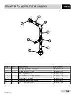
Страница 61: ...ex 3 4 M to 1 2 Brass 04730 002 56 27 2 3 Nipple Brass 1 2 X 3 NPT 04730 004 20 10 3 1 Elbow 1 2 NPT 90 Brass 04730 011 42 96 4 1 Tee 1 2 FNPT X 1 2 FNPT 1 4 FNPT 04730 002 22 56 5 1 Union 1 2 X 1 2 Brass 04730 003 62 44 6 1 Fitting 1 4 Barb 1 4 MNPT Swivel 04730 011 95 41 7 1 Hose 1 2 ID X 58 LG Blue 05700 004 19 91 ...

Страница 62: ...4730 002 56 27 2 3 Elbow 3 4 Street Brass 90 Degress 04730 206 04 34 3 1 Regulator Pressure 3 4 06685 011 58 22 4 1 Nipple 3 4 NPT X 1 3 8 Closed Brass 04730 207 34 00 5 1 Valve 3 4 220V Solenoid 04810 100 03 18 6 1 Nipple 1 2 Closed Brass 04730 207 15 00 7 1 Elbow 90 Degree 1 2 Street Brass 04730 206 08 00 2 2 1 4 5 6 7 3 ...

Страница 63: ...M BREAKER REPAIR PARTS KITS 4810 200 03 18 Complete 110 Volt Solenoid Valve Assembly 1 2 04810 100 12 18 Coil Housing only 06401 003 07 43 Complete 240 Volt Solenoid Valve Assembly 1 2 04810 100 09 18 Coil Housing only 06401 003 07 44 Complete Vacuum Breaker Assembly 1 2 NPT 04820 003 06 13 ...

Страница 64: ... 1 per machine 05700 002 56 75 Plug 1 8 NPT Brass 3 per Rinse Injector 04730 209 07 37 Rinse Injector Gasket 2 per machine 05330 111 42 81 10 18 15 14 20 13 11 10 10 10 9 17 16 5 7 7 6 10 19 3 2 6 8 9 17 3 17 1 5 1 4 2 9 17 DETAIL A FINAL RINSE ARMS MANIFOLD DETAIL B WASH ARMS MANIFOLD ...

Страница 65: ...ip Retaining Rinse Head Bushing 05340 112 01 11 12 4 Rinse Arm Washer 05330 011 42 10 13 2 Bushing Rinse Head 05700 021 33 84 14 2 Rinse Arm 05700 003 58 94 15 4 Plug Rinse Arm 04730 609 04 00 16 1 Lower Wash Manifold 05700 031 46 00 17 2 Bearing Assembly 05700 021 35 97 17a 1 Hub Nut 05700 011 35 94 17b 1 Hub Bushing 05700 011 35 96 17c 1 Hub Spindle 05700 011 35 95 17d 1 Ring Retainer 05340 011 ...

Страница 66: ...59 07610 003 61 42 T PARTS TEMPSTAR VENTLESS SYSTEM ASSEMBLY ...

Страница 67: ...004 18 04 7 1 Gasket Heat Exchanger 05330 004 18 22 8 1 Gauge 06680 011 86 42 9 1 Coil Box Back 05700 004 18 03 10 12 Bolt 1 4 20 X 3 8 Hex 05305 274 20 00 11 1 Bracket Vacuum Breaker 05700 004 18 91 12 1 Shroud Hear Exchanger 05700 004 18 92 13 6 Nut Lock 10 24 S S Hex w Nylon 05310 373 01 00 14 6 Washer Flat 05311 173 02 00 15 2 Fan 3 62 Square 85 236V AC Corrosion Resistant 05999 004 19 46 16 8...

Страница 68: ... Interlock Weldment 05700 004 23 15 4 1 Soleniod Horizontal 1 Push 04820 004 24 11 5 1 Spring Comp 05935 004 24 10 6 1 W Base Door Interlock Box 05700 004 24 25 7 8 Screw 3 8 Pan Head 05305 171 02 00 8 8 Washer Flat 10 05311 173 02 00 9 2 Locknut 1 4 20 05310 374 01 00 10 2 Washer S S 1 4 20 I D 05311 174 01 00 11 1 Fitg 3216 Liqtite Blk 05975 011 59 50 12 2 Connector 2 Conductor 05935 004 03 49 1...

Страница 69: ... 05700 000 35 05 Solenoid Electrical Interlock Option 04810 100 61 33 Relay 05945 111 47 51 OTHER DOOR INTERLOCK SDI COMPONENTS NOT SHOWN Transformer Mounting Bracket 05700 031 62 82 Exhaust Fan Control 2 Din Rail 05700 002 36 09 415 440 460V Transformer 05950 111 65 93 380V Transformer 05950 111 64 17 Exhaust Fan Control Delay Timer 05945 011 65 44 Transformer Mounting Box 05700 002 10 01 Transfo...

Страница 70: ... Hi Limit 05930 011 49 43 9 1 Liquid Level Control 06680 200 08 21 10 1 Probe water level sensing 06680 200 02 68 11 1 Magnet Door 05930 111 51 68 12 6 Glide Door Edge 05700 111 33 59 13 2 O Ring Wash Manifold 05330 111 35 15 14 1 Relay Control 240V 50 60Hz 05945 111 47 51 15 1 Seal Mechanical Pump S S Pumps 05330 002 34 22 16 1 O Ring Wash Pump Gasket 05330 002 81 83 17 1 Switch Door Magnetic Ree...

Страница 71: ...7 40 00 5 1 Tee 1 1 2 Brass 04730 011 69 93 6 1 Reducer 1 1 2 x 1 4 Hex Brass 04730 002 55 76 7 1 Union 1 4 Modified 05700 001 16 52 8 1 Nipple 1 1 12 Brass Close 04730 207 40 00 9 1 Tee 1 1 2 Brass 04730 011 69 93 10 1 Elbow 1 1 2 NPT Female 04730 206 32 00 11 1 Nipple 1 2 Close Brass 04730 207 15 00 12 1 Valve Check 1 2 04820 002 55 77 13 1 Reducer 1 2 x 1 4 Brass 04730 003 62 16 14 1 Solenoid V...

Страница 72: ... Wash Heater Cover 05700 004 07 92 2 1 Liquid Tight Fitting Large 05975 011 65 51 3 1 Conduit Fitting 45 1 2 05975 011 45 23 4 2 Lock Nut 6 32 Hex 05310 373 03 00 5 1 Thermostat 05930 003 13 65 6 1 Conduit Fitting 90 1 2 05975 011 45 14 7 1 Liquid Tight Fitting Small 05975 011 49 03 1 2 3 4 5 6 7 ...

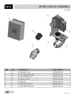
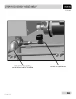
Страница 73: ...66 07610 003 61 42 T PARTS DRAIN QUENCH ASSEMBLY Continued Connect 1 1 2 drain plumbing elbow can be removed if not needed Connect 1 4 cold water line ...

Страница 74: ...07610 003 61 42 T 67 SCHEMATICS SOLID STATE 208 230V 50 60 HZ 1 3 PHASE TEMPSTAR TOP MOUNT W CYCLE SWITCHES ...

Страница 75: ...07610 003 61 42 T TEMPSTAR 208 230V 50 60 HZ 1 3 PHASE SCHEMATICS TEMPSTAR TOP MOUNT W CYCLE SWITCHES 68 ...

Страница 76: ...69 07610 003 61 42 T SCHEMATICS SOLID STATE 460 V 60 HZ 3 PHASE TEMPSTAR TOP MOUNT W CYCLE SWITCHES ...

Страница 77: ...70 TEMPSTAR 460 V 60 HZ 3 PHASE SCHEMATICS TEMPSTAR TOP MOUNT W CYCLE SWITCHES ...

Страница 78: ...71 07610 003 61 42 T SCHEMATICS SOLID STATE LT NB 208 230V 50 60HZ 1 3 PHASE TEMPSTAR TOP MOUNT W CYCLE SWITCHES ...

Страница 79: ...72 TEMPSTAR LT NB 208 230V 50 60HZ 1 3 PHASE SCHEMATICS TEMPSTAR TOP MOUNT W CYCLE SWITCHES ...

Страница 80: ...73 07610 003 61 42 T SCHEMATICS TEMPSTAR NB LT 460V 50 60 HZ 3 PHASE TOP MOUNT UNIVERSAL TIMER ...

Страница 81: ... 61 42 T TEMPSTAR S 208 230V 50 60 HZ 1 3 PHASE SCHEMATICS TOP MOUNT UNIVERSAL TIMER TEMPSTAR STEAM TEMPSTAR STEAM ELCTRICAL DIAGRAM ELCTRICAL DIAGRAM 208 230 VOLT 50 60 Hz 1 3 PHASE 208 230 VOLT 50 60 Hz 1 3 PHASE ...

Страница 82: ...75 07610 003 61 42 T SCHEMATICS SDI OPTIONS ...

Страница 83: ...76 07610 003 61 42 T DRAIN QUENCH OPTIONS SCHEMATICS ...

Страница 84: ... F RISE BOOSTER WASH MOTOR 230V 208V 3 4 HP 5 7 A 3 4 HP 5 7 A WASH HEATER 4 1 KW 19 7 A 5 KW 21 7 A RINSE HEATER 10 5 KW 50 4 A 12 9 KW 56 1 A TOTAL LOAD 75 8 A 83 6 A 70 F RISE BOOSTER 208 230 Volt 60 Hz 1 Phase 24 3 A 70 F RISE BOOSTER 4000897 Conforms to UL Std 921 Conforms to CSA Std C22 2 No 168 Intertek Jackson Technical Manual Addendum Tempstar units that are manufactured with the above re...

Страница 85: ......

Страница 86: ...79 TEMPSTAR LT NB VENTLESS S Technical Manual Rev T P N 7610 003 61 42 Issued 11 11 08 Revised 01 11 16 Jackson WWS Inc 6209 N US Hwy 25E Gray KY 40734 USA 1 888 800 5672 www jacksonwws com ...

Отзывы: