23
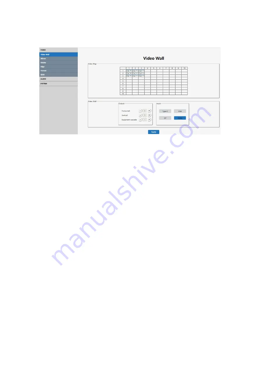
7.5.2 Video Wall Setting
Note: This interface is used to set up video walls or cascading controllers.
Interface Introduction:
(1)
Video Map
: To identify the location of the output port mapping/routing, you can
change the output port position through the drop-down menu. The position of
output port mapping “Map1” to “Map9” in the same cascading layer is consistent
no matter how the HDMI Out ports are assigned. The rule for the "Port Map"
position is from left to right, from top to bottom as shown.
(2)
Output
: # of screens in horizontal and vertical position & # of cascading video
wall controllers
(3)
Input
: Source selection for the video wall.
(USB Type-C, VGA, DP, HDMI)
(4) Default 3x3 Video Wall Configuration: JTECH-VW09 can also accomplish 4x3
5x4 5x5 6x6 7x7 8x8 and max 10x10 video walls through cascading units.
(5) The max # of displays in the horizontal direction is 10.
(6) The max # of displays in the vertical direction is 10.
(7) The max cascade layer amount is 12 layers
(12 Cascading JTECH-VW09)
(8)
Note:
The parameters can be set up by clicking the "+ " or "-" button in the
‘Output’
section. When a source illuminates blue in the
‘Input’
section, it
indicates that current source input is selected.
Operating Instructions
Ex 1
:
Select DP port as input source to make a 3x3 video wall via 1 JTECH-VW09.
(1) In the Output section, set both the "Horizon" and "Vertical" settings to “3” and
the "Equipment Cascade" to “1”.
(2) Then click "DP" in the Input section.
In the Video Map section, set the output ports according to TV 1-9. For example: In
the Video Map section, assign the output ports as designated in the picture below:
Map 1 – Out 8; Map 2 – Out 6, Map 3 – Out 3; Map 4 – Out 2, Map 5 – Out 1; Map 6
– Out 9; Map 7 – Out 5; Map 8 – Out 4; Map 9 – Out 7


