


7
6X-1050a
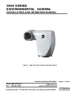
3960 CAMERA
INSTALLATION AND OPERATION
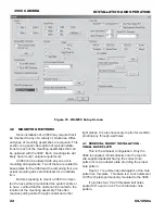
Figure 4. Wall Mount Arm
Figure 5. Pole Mount
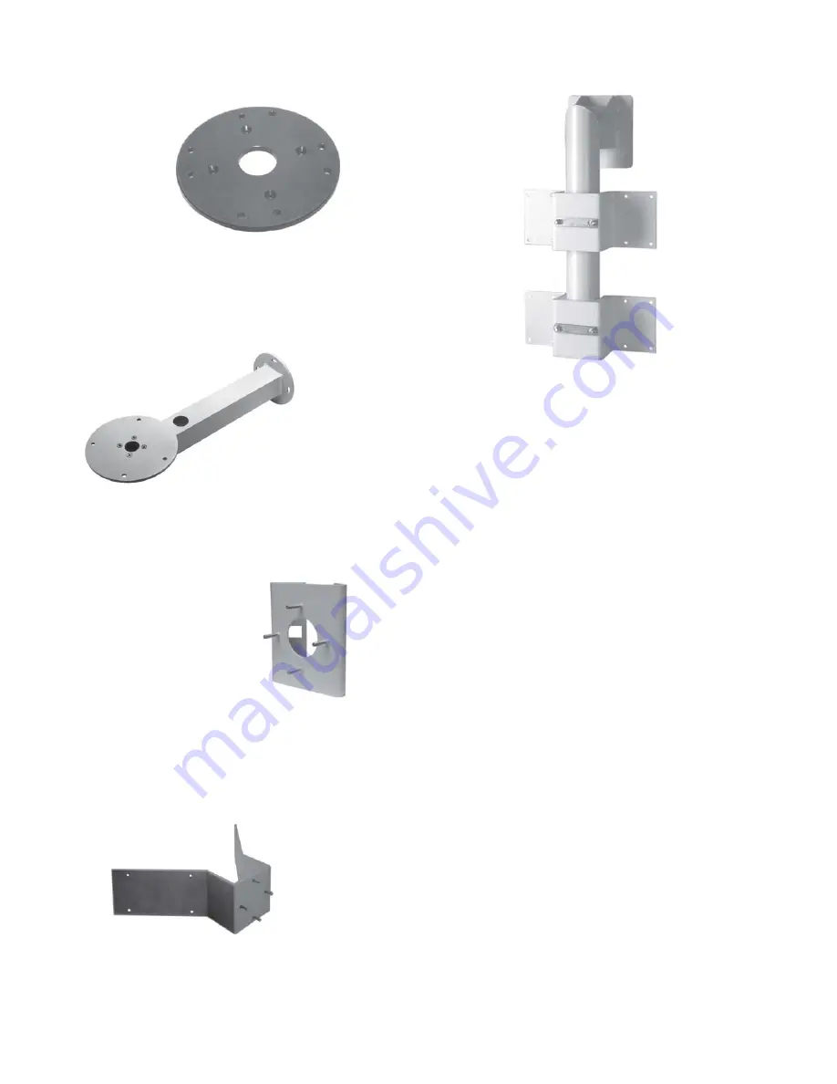
Figure 6. Corner Mount
Figure 7. Parapet Mount
The pressure relief valve should be lifted off its
seat during purging of the camera. This aids in the
flow of gas through the housing while purging
moisture laden air from inside.
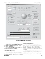
The mounting base for the 3960 has a four-
hole pattern for attachment to a pedestal, mounting
arm, or other suitable base. High quality (grade
316) stainless steel bolts and lock washers should
be used. An additional add-on base plate is avail-
able to provide additional hole patterns on a larger
diameter.
A 3960 can be mounted in any one of six
mechanical configurations depending on the mount-
ing accessories supplied. The model number
defines the mounting equipment supplied as part of
the 3960. Table 2 shows the mounting items sup-
plied for each of the mounting configurations avail-
able with a 3960.
2.0 INSTALLATION
This section covers the general requirements
of installing the 3960 including cabling, power
requirements, and pressurization considerations. In
addition to the actual installation requirements, this
section covers a number of other items including
static discharge protection and proper shipping and
handling of the 3960.
Section 4 at the rear of this manual covers the
various mounting brackets, their dimensions, and
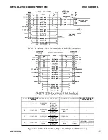
Figure 3. Optional LPEDD Adapter Plate


