


2
6X-1050a
3960 CAMERA
INSTALLATION AND OPERATION
LIST OF SECTIONS
LIST OF FIGURES
LIST OF TABLES
SECTION
TITLE
PAGE
1.0
GENERAL DESCRIPTION
1
1.1
Electrical Characteristics
1
1.2
Mechanical Characteristics
1
2.0
INSTALLATION
7
2.1
Unpacking and Receiving Inspection
7
2.2
Static Discharge Protection
8
2.3
Equipment Supplied
9
2.4
Equipment Required but Not Supplied
9
2.5
Cabling Requirements
10
2.6
Power Requirements
15
2.7
Mounting Requirements
15
2.8
Installation Procedure
17
2.9
Preparation for Shipment and Storage
17
3.0
Operation
18
3.1
Local Panel Control
18
3.2
Local Laptop PC Control
18
3.3
WinMPC Installation Setup
18
4.0
Mounting Methods
22
4.1
Pedestal Mount Installation - Small Base Plate
22
4.2
Large Base Plate Installation
24
4.3
Wall Mount Installation
24
4.4
Pole Mount Installation
25
4.5
Corner Mount Installation
25
4.6
Parapet Mount Installation
25
F IG U RE
T IT L E
PAG E
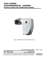
1
H ig h P e rfo rm a nc e E nviro nm e nta l C a m e ra
1
2
M o d e l N um b e r Inte rp re ta tio n D ia g ra m
6
3
O p tio na l L P E D D A d a p te r P la te
7
4
W a ll M o unt A rm
7
5
P o le M o unt
7
6
C o rne r M o unt
7
7
P a ra p e t M o unt
7
8
D im e ns io ns , M o d e l 3 9 6 0 C a m e ra
9
9
Typ ica l 2 3 2 /4 2 2 C o nve rte r
11
1 0
P ino ut D ia g ra m , 3 9 6 0 P ig ta il C o nne c to r
11
11
Inte rco nne ctio n D ia g ra m , Typ ic a l Te st S e tup
1 2
1 2
Te st C a b le , C TC -3 0 , 11 5 V a c
1 3
1 3
Te st C a b le , C TC -3 5 , 2 4 V a c
1 4
1 4
C a m e ra M o d ule R e a r P a ne l
1 5
1 5
M o d e l 9 3 0 0 L o c a l C o ntro l P a ne l
1 5
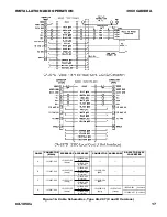
1 6
C a b le S c he m a tic , Typ e C A -2 9 7 A , B , C a nd D
1 6
1 7
D im e ns io ns , 3 9 6 0 Sta nd a rd B a se
1 9
1 8
D im e ns io ns , O p tio na l L a rg e B a s e
1 9
1 9
A b o ut W inM P C G U I S c re e n
2 0
2 0
C o hu W inM P C H o m e S c re e n
2 1
2 1
W inM P C S e tup S c re e n
2 2
2 2
D im e ns io ns , W a ll M o unt A rm
2 4
2 3
D im e ns io ns , P o le M o unt
2 5
2 4
D im e ns io ns , C o rne r M o unt
2 6
2 5
D im e ns io ns , P a ra p e t M o unt
2 7
2 6
Ins ta lle d P a ra p e t M o unt
2 7
TABLE
TITLE
PAGE
1
Specifications
4
2
Mounting Configurations
5
3
Items Supplied
9
4
Items Required but Not Supplied
9
5
System Connectors
9
6
Pin Functions, 24 V ac Cable
11
7
Pin Functions, 115 V ac Cable
12
FCC STATEMENT
This equipment has been tested and
found to comply with the limits for a
Class A Digital Device, pursuant to Part
15 of the FCC Rules. These limits are
designed to provide reasonble protec-
tion against harmful interference when
the equipment is operated in a com-
mercial environment. This equipment
generates, uses, and can radiate radio
frequency energy and, if not installed
and used in accordance with the in-
struction manual, may cause harmful
interference to radio communications.
Operation of this equipment in a resi-
dential area is likely to cause harmful
interference in which case the user will
be required to correct the interference
at his own expense.
CAUTION: Changes or modifications
to this device not expressly approved
by Cohu Electronics could void the
user’s authority to operate the device.
This device complies with Part 15 of the
FCC Rules. Operation is subjected to the
following two conditions: (1) this device
may not cause harmful interference and
(2) this device must accept any interfer-
ence received, including interference
that may cause undesired operation.


