1.
Clean and lubricate the fitting surfaces between the bearing bracket (228C) and suction casing
(110F).
2.
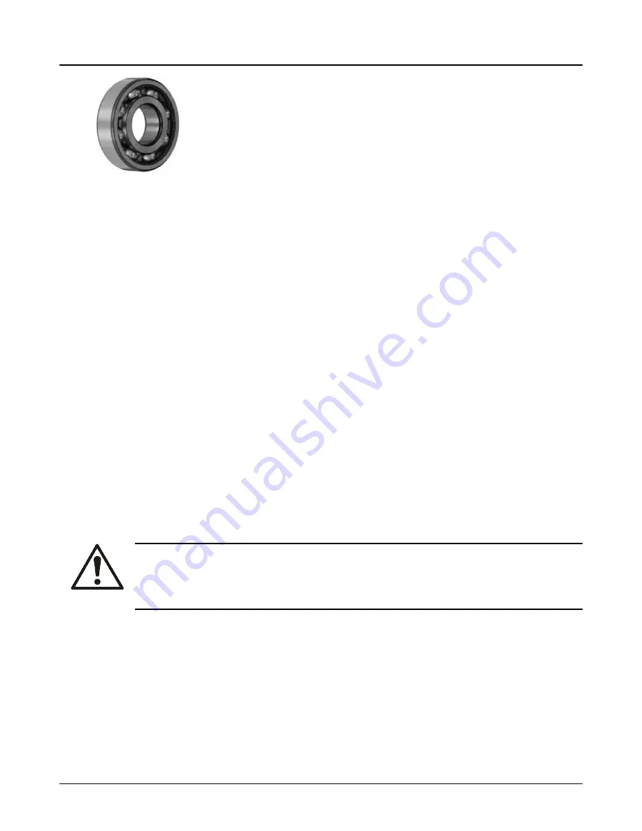
Preheat the new bearing (112) to a maximum of 230°F (110°C) and slide it onto the shaft (122).
3.
Tighten the new shaft nut (136A) while the bearing is still hot, then turn it back one quarter of a turn.
4.
After the bearing cools down, pack the bearing completely with grease making sure that grease
gets under the cage.
When the pump is started the bearing will run hot for several minutes until the excess grease is
purged. It will then return to a normal operating temperature. When the bearing is installed in the
bearing housing, the cavities on either side should be filled with grease for about 1/3 of the volume.
5.
Fit the bearing bracket (228C) and insert the seal cover (184).
6.
Screw the bearing cover (119) to the bearing bracket (228C).
7.
Grease the contact surface of the thrower (248) and bring the thrower or heat flinger (123B) into
position on the spacer sleeve (157).
The thrower sits in a groove on the spacer sleeve while the heat flinger blades need to be posi-
tioned approximately 0.75 in. (1.91 cm) from the bearing cover studs (356C).
8.
Align the surfaces of the pump feet. Make sure the pump is on an even surface.
9.
Lay the discharge casing (100D) horizontally so that you can insert the shaft (122).
10. Place the pre-mounted unit on the discharge casing (100D) and tighten the nuts (425) firmly. See
the Torque values table.
11. Rotate the shaft (122) and make sure it runs smoothly.
12. Replace the flinger guards (499) if applicable.
6.6.4 Reassemble the pump body
1.
Invert the pump. Make sure that the free shaft points upwards and is vertical.
2.
Lubricate the shaft (122). Make sure that the lubricant is compatible with the shaft O-ring material.
3.
Check the position of the impeller. Insert a diffuser (150L) and slide the impeller (101) until it is im-
pact.
CAUTION:
If a pump is assembled with new impellers, the first and last stages are always provided with
full diameter impellers. If only one impeller is available with the full diameter, it must be used as
the first stage.
Assembly work always starts with the final stage.
4.
Remove the impeller and diffuser once more, then insert the O-ring (497D), and re-insert the diffus-
er (150L/150).
5.
Insert the key (178 or 178E) for the impeller that you plan to mount.
6.
Mount the impeller (101).
Note that as the O-ring (497D) presses on the diffuser (150L/150), the setting will not be correct at
first.
7.
Generously grease the O-ring (412K) with silicon grease and grease the stage casing (100G). Do
not twist the O-ring.
8.
Place the stage casing (100G) on levelly and force it down sharply. Hit it with a plastic hammer until
it impacts.
9.
For the ES configuration, assemble the pump down to the intermediate bearing housing (134C).
6.6 Reassembly
54
Model 3355 Installation, Operation, and Maintenance Manual
Содержание Goulds Pump 3355
Страница 1: ...Installation Operation and Maintenance Manual Model 3355 ...
Страница 2: ......


