


Operating manual: PHOTOMETER FM-4 6
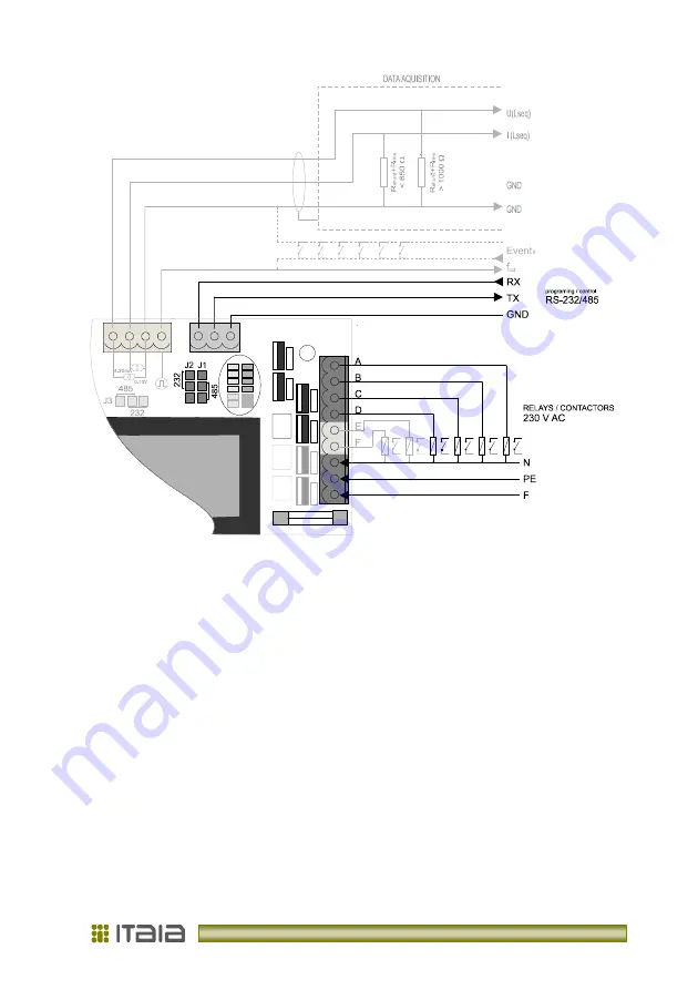
Picture 2: Photometer connection
2. 4. Onboard Indicators
From back side visible LED indicators on PCB indicate current light conditions - green and
contactor output status – red (see Picture 1). Other LEDs are status indicators and have no
meaning for the user.
2. 4. 1. Serial Communication Port
The photometer's selectable communication port can be configured for RS-232 or RS-485.
Set jumpers J1... J3 to select the protocol. Connection distance can be up to 20 m for RS-
232 and 300 m for RS-485. Communication supports the complete set of photometer’s
functions, setup parameters and output values.
When serial communication is used for on-line data transfer always choose RS-485. Use
RS-232 for parametric setup or laboratory use only.
Содержание Photometer FM-4
Страница 2: ......
Страница 23: ...V 1 2 rev 12 2012...
Страница 24: ...Litostrojska cesta 44 d SI 1000 Ljubljana T 386 1 514 18 00 F 386 1 514 18 04 info itaia si www itaia si...