Operating manual: PHOTOMETER FM-4 5
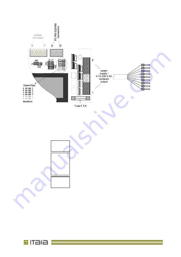
Picture 1: Connectors behind the rear cover
pin
port
voltage
description
1
L-
power
230 V AC
power
2
PWR
ground
/
grounding
3
N-
power
230 V AC
power
4
out F
230 V AC
contactor out. F
5
out E
230 V AC
contactor out. E
6
contactor
out D
230 V AC
contactor out. D
7
out
out C
230 V AC
contactor out. C
8
out B
230 V AC
contactor out. B
9
out A
230 V AC
contactor out. A
10
PC
GND
0 V DC
programming/control
11
RS 232
RX
±
12 V DC
programming/control
12
/485
TX
±
12 V DC
programming/control
13
LOGIC I/O
f
port
0-15 V DC
freq./range
out
; Event
in
14
analog
GND
0 V DC
15
analog
I
out
4-20 mA
current output
16
analog
U
out
0-10 V DC
voltage output
Table 1: Pin out and description
Содержание Photometer FM-4
Страница 2: ......
Страница 23: ...V 1 2 rev 12 2012...
Страница 24: ...Litostrojska cesta 44 d SI 1000 Ljubljana T 386 1 514 18 00 F 386 1 514 18 04 info itaia si www itaia si...


