iSMA-B-LP Room Panel/Modbus
version 1.3
www.gc5.pl
Page 42 / 121
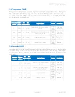
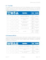
WARNING!: The register values from 4 to 6 (1-3 Speed Fan without AUTO mode) have to be
set when fan works in Local Mode (see
FanLocalMode
).
7.4
FAN
_
MODE
_
NAME (41604-41612
)
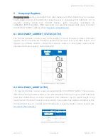
For user-friendly use, FAN_MODE register value is displayed on LCD as a text instead of
numeric value. There are six 32-bit registers assigned with six different fan modes, which
can contain up to 4 characters according to the ASCII code (see example in
Temperature
Name
). The value of 32-bit register is displayed on 8-segment display block as a text. In case
when particular ASCII code value is 0(NULL), the character is not displayed. Lower case
characters are automatically changed into upper case characters.
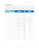
Register address
Default name
Corresponding Fan mode register value
41604
OFF
0
41606
AUTO
1
41608
I
2
41610
II
3
41612
III
4
Table 19 Fan name registers
7.5
FAN
_
CONFIGURATION (41614)
7.5.1
FAN
_
CURRENT
_
SPEED
_
VISIBILITY (Register 41614, bit 0)
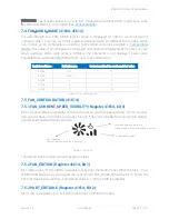
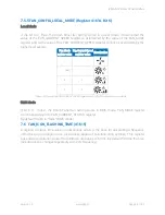
Bit 0 is responsible for activation or deactivation Fan Current Speed visibility. If bit 0 is active
Fan Current Speed is visible as a group of Icons. The icons indicate fan activity (run status),
actual speed and auto/manual mode.
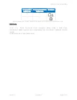
Figure 19 Fan Icon
The default value is 1(fan current speed is visible).
7.5.2
FAN
_
EDITION (Register 41614, bit 1)
Bit 1 determines if FAN_MODE is editable locally from the Room Panel. When the bit is
“true”
the Fan Edit Submenu is active and the user can set FAN_MODE. When the bit is
“false”
the
Fan Edit Submenu is inactive. The default value is 1 (FAN_MODE is editable).
7.5.3
PART_EDITABLE (Register 41614, Bit 2)
Bit 2 switches between Fan Full Edition and Fan Part Edition modes.
Run indication
(symbol rotates when a fun is running)
Auto/manual mode indication
(Hand symbol when manual mode is active)
Actual Speed symbol


