iSMA-B-LP Room Panel/Modbus
version 1.3
www.gc5.pl
Page 22 / 121
entering appropriate values to assigned registers.
4.8
LCD Display
The Room Panel iSMA-B-LP is equipped with 2.
3” LCD display with backlight.
By default LCD display is turned ON (when the device is powered) and basic parameters
from in-built sensors together with user defined parameters are shown in the Main Menu.
The register DEVICE_CONFIGURATION bit 11 is responsible for LCD display and Key Pad
activation.
When the bit is
“false”,
LCD display and Key Pad work in normal mode (parameters and
actual sensor values are displayed, submenus are visible and editable etc.).
If the bit is
“true”
, LCD display and Key Pad is deactivated. The Room Panel works as a
simple sensor. (CO
2
sensor, temperature sensor, humidity sensor
–
depending on Room
Panel version, see table 3).
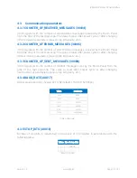
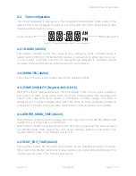
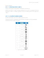
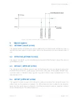
Figure 14 LCD display general view
4.8.1
Icons displaying.
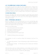
There are many different Icons which are available on the Panel Display. User can choose
which Icon is dedicated for visualization of a particular process. Every single Icon can be
controlled by a higher level system. There are two Modbus registers which are responsible

