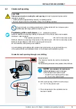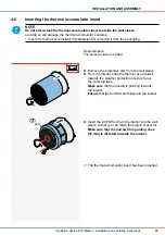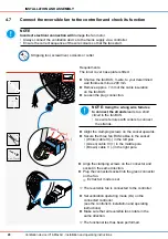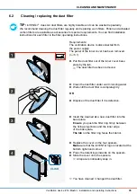
NOTE:
Only install the fan BUS in a de-energised state.
Disconnect the power supply to the controller when connecting the cable to the control unit
(sMove programming unit or Clust-Air module CAM17).
Only connect the cable to the control unit when it is de-energised. Instructions for installing
the fan BUS (including maximum cable lengths) can be found in the installation and operating
instructions supplied with the controller.
Wall slot cutter, hammer, chisel, fan BUS (3-wire)
Requirements:
The wall opening is ready.
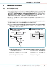
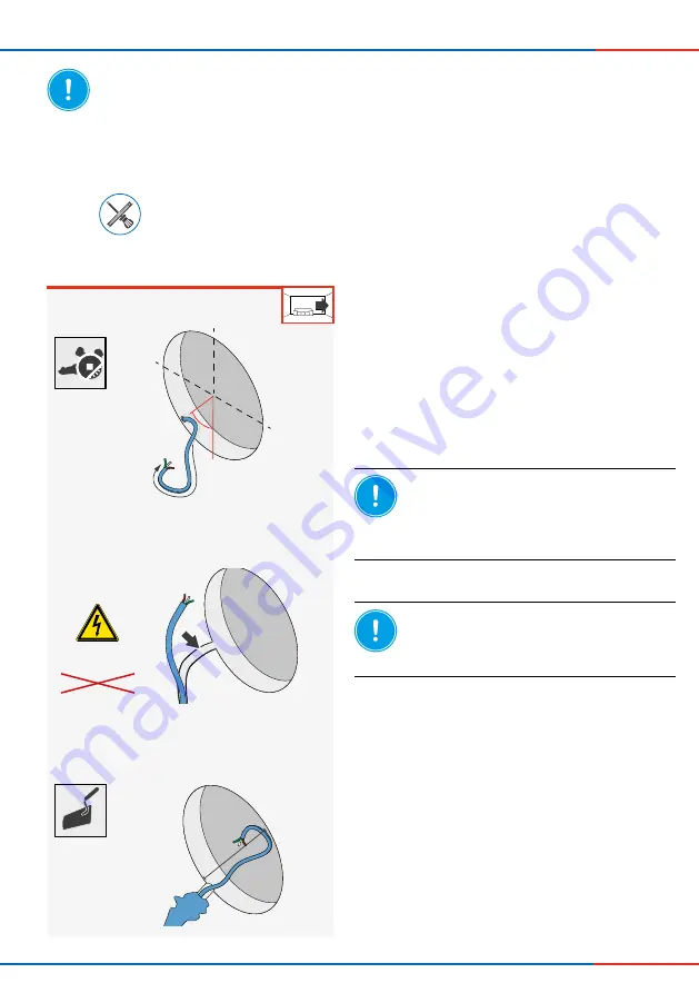
45°
L = 500 mm
> 5
00
m
m
21
INSTALLATION AND ASSEMBLY
Ventilation device iV14-MaxAir
•
Installation and operating instructions
►
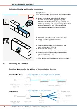
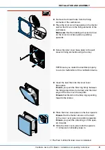
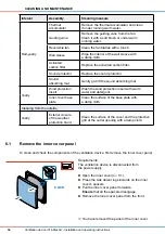
Route the fan BUS, 3-wire (stranded wire) from
the control unit to the wall opening of the ventilation
device.
►
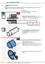
Re-plaster the plaster/masonry slot.
Ensure
that the cable end protrudes approximately
500 mm into the interior space.
NOTE:
The cable sheath provides
no resistance when laid under plaster.
Short circuit and cable fire!
• If necessary, lay the cable in the conduit.
The fan BUS is installed.
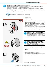
►
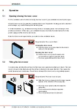
Mill the plaster/masonry slot between the control
unit and the wall opening.
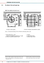
Make sure
that the plaster/wall slot for the cable to
the control unit is positioned at a 45° angle to the
bottom left of the wall opening.
►
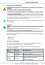
Seal off the wall opening from the inside and outside
until you are ready to install the wall sleeve.
The plaster/wall slot for the cable (fan BUS)
has been created.
NOTE:
The use of too small a cable
cross-section
leads to too great a voltage
drop and/or contact is not guaranteed!
• For the fan BUS, use a cable cross-section
of at
least 0.75 mm²
.
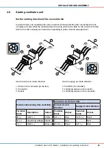
6 – 16 V DC
230 V AC

