


8
A
_ _ _ AVERAGING PARAMETERS
scrolls across the display
and toggles with
SKIP
. Press
P
to skip to 6.5, or the
button and then
P
to
ENTER
averaging setup.
B
_ _ _ AVE SAMPLES
scrolls across the display and toggles
with the currently selected averaging. Use the
and
buttons to alter the signal averaging and then press
P
.
Increasing the number of samples will stabilise measurement,
but it will also slow down response rates.
C
_ _ _ AVE WINDOW
scrolls across the display and toggles with
the currently selected averaging window value.
Use the
and
buttons to alter the signal averaging
window, and then press
P
.
If your input signal contains large noise spikes then you can
increase the size of averaging window to ensure that these pulses are still averaged. However, increasing the
averaging window too far will reduce the ability of the indicator to respond quickly to real changes in input signal.
Setting the averaging window to zero will turn off the window mode and give continuous averaging as per the se-
lected averaging samples.
6.5
–
Analogue output setup:
If your indicator does not have this option installed then you will not view this section - setup will continue at 6.6.
A
_ _ _ ANALOG OUTPUT SETUP
scrolls across display and toggles with
SKIP
.
Press
P
to skip to 6.6, or the
button and then
P
to
ENTER
analogue output setup.
B
_ _ _ LOW SCALE VALUE FOR ANALOG OUTPUT
scrolls across the display and toggles with the current
selection. Use the
and
buttons to enter your cal low position, and then press
P
.
This sets the display value for cal low (as at 6.5E).
C
_ _ _ HIGH SCALE VALUE FOR ANALOG OUTPUT
scrolls across the display and toggles with the current
selection. Use the
and
buttons to enter your cal high position, and then press
P
.
This sets the display value for cal high (as at 6.5F).
D
_ _ _ CALIBRATE ANALOG OUTPUT?
scrolls across the display and toggles with
SKIP
.
If you do not wish to calibrate your analogue output, press
P
now.
If you would like to calibrate your analogue output:
Set the analogue output board jumper in the correct position (see Section 4) and connect a mA or volt meter
across the analogue output connector (see 5.3).
Press the
button to select
ENTER
and then
P
to enter calibration mode.
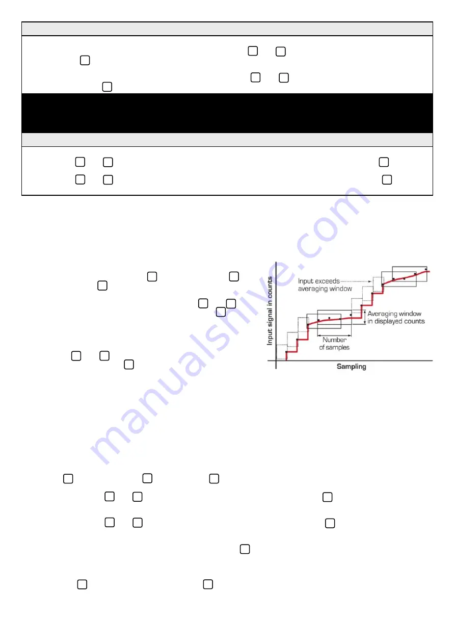
6.4
–
Averaging:
Your indicator has input signal averaging, guaranteeing stable measurement. If the input exceeds the averaging window
value it will not average, ensuring fast response.
If you selected AUTO in 6.3A:
B
_ _ _ APPLY LOW INPUT SIGNAL –
–
–
–
ENTER LOW DISPLAY VALUE
scrolls across the display.
Apply the required low input signal to the indicator. Using the
and
buttons, enter your low end display value.
Then press
P
to accept.
_ _ _ APPLY HIGH INPUT SIGNAL –
–
–
–
ENTER HIGH DISPLAY VALUE
scrolls across the display.
Apply the required high input signal to the indicator. Using the
and
buttons, enter your high end display
value. Then press
P
. If calibration is successful, the indicator will return to the operational display.
_ _ _ CALIBRATION FAILED
A calibration failure results when the indicator cannot detect any change in input signal during the calibration
procedure. After viewing this message you will be redirected to the operational display. Check your input
signal and connections, and then repeat the process.
If you selected MANUAL in 6.3A:
C
_ _ _ ENTER DISPLAY VALUE FOR (X)
scrolls across. (X=0mA/4mA/0V, depending on your selection in 6.2C.)
Using the
and
buttons, enter your display value for the selected low input signal. Then press
P
.
_ _ _ ENTER DISPLAY VALUE FOR (X)
scrolls across. (X=20mA/2V/10V, depending on your selection in
6.2C.) Using the
and
buttons, enter your display value for the selected high input signal. Then press
P
to
accept the new calibration values and return to the operational display.


