


18 of 43
2020-5-22
UG2020-11 REF-Vacuum-C101-2ED User Guide
Here are the steps needed to run the motor:
1.
Connect iMOTION
TM
Link’s 8-pin cable to J2 with default pin order, and connect PC-USB connector
iMOTION
TM
Link. (Or connect third party isolated USB-to-UART cable to J1).
2.
Use MCEWizard to enter the target motor’s system and operating parameters, as well as evaluation board’s
hardware parameters, which will then be used to calculate the digital parameter set of the controller
representing the complete motor drive system.
3.
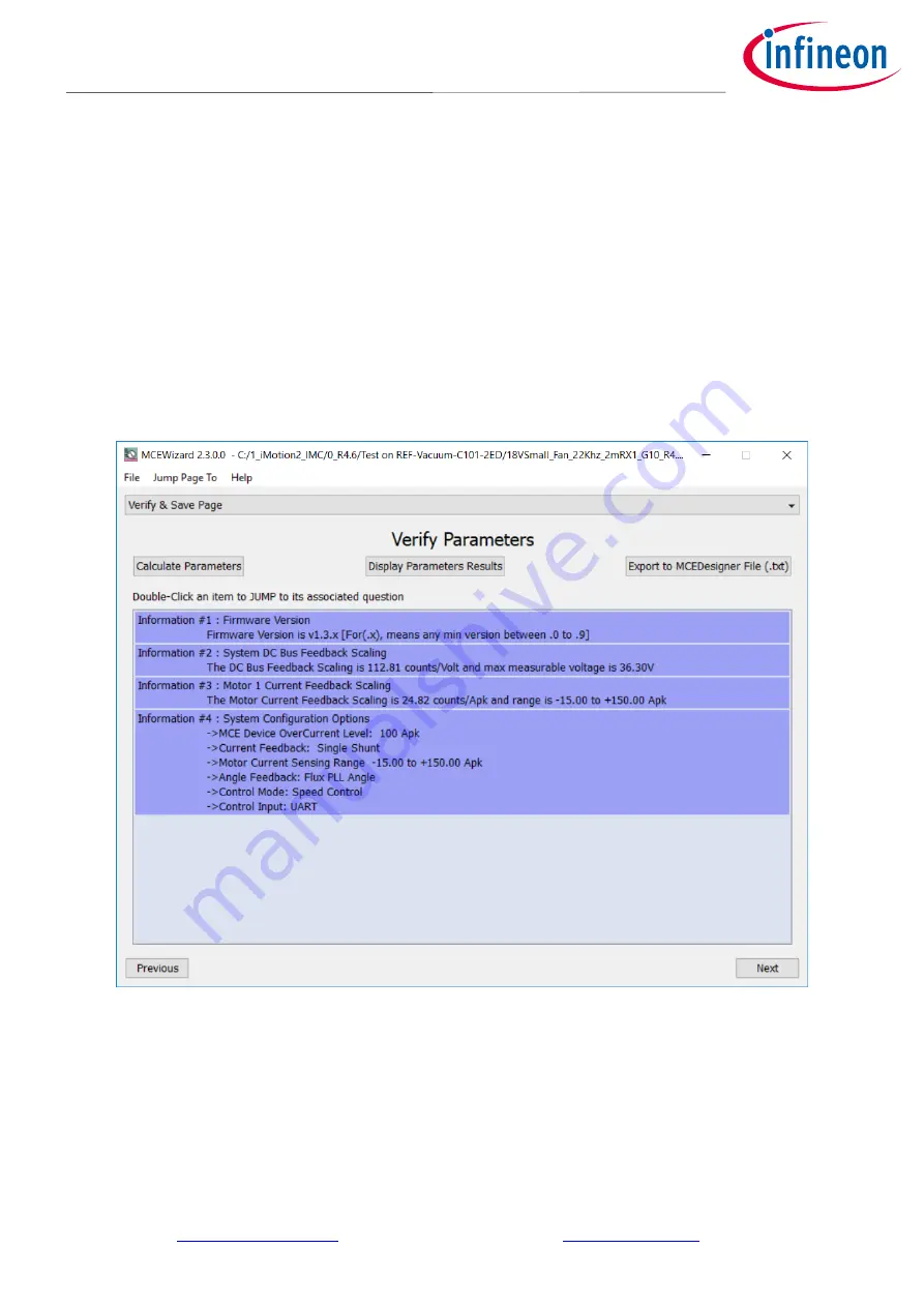
After system and operating parameters are set, go to the “Verify & Save Page” and click on “Calculate” button.
If no errors are reported, then save the drive parameter set into your project directory by clicking “Export to
Designer file (.txt)” ( Figure 10); if an error is detected, double-click on the error message (highlighted in RED)
and adjust the related parameter. Saved drive system parameter file will be later used by the MCEDesigner in
step 9.
(Please refer to
MCEWizard_V2.3.0.0 User Guide.pdf
for more details, which is in MCE
Wizard’s
install path)
Figure 10
MCEWizard Verify and Save page
4.
Connect 24 V power supply and UVW outputs to the motor.
5.
Turn on 24 V power supply or connect 6S ~ 7S Li battery, green LED1 ON.
6.
Start MCEDesigner tool and open MCEDesigner default configuration file (.irc) for IMC101T device
(IMC101T_Vxxx.irc) by clicking “File” > “Open”.
(IMC101T_Vxxx.irc file is included in downloaded
“
IMC101T MCE Softwa
re Package”
)
7.
MCEDesigner should automatically connect to the REF-VACUUM-C101-2ED board using default COM port
(Indicated by green circle next to “COMx Up” status in the bottom frame of the MCEDesigner GUI)
. If it cannot


