background image

14

STV50 ed 09/08 

VICTRIX 50 Rev. 002 

10

8

4

12

9

1

11

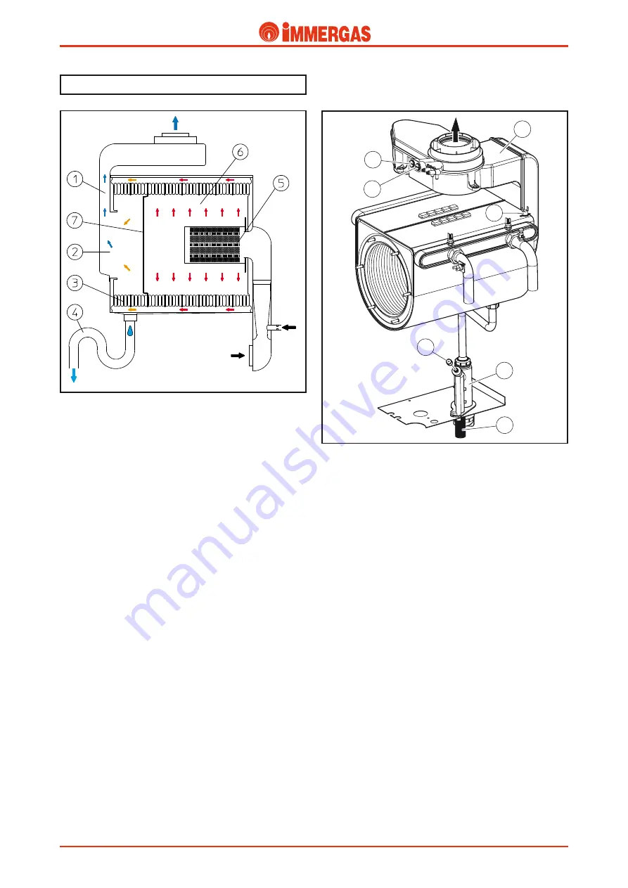
Condensate drain trap (4).

Collects the condensate that forms during boiler functioning 

from the bottom of the module.

Its outlet is connected to the draining pipe (11) towards which 

the passage of water is allowed but not the passage of fumes, 

which could occur following obstruction of the evacuation 

pipes.

The height of the column of water in the siphon is in fact 

greater than the pressure detected inside the sealed chamber 

(module)

 with the fan at maximum speed and the evacuation 

pipes blocked at functioning limits.

This, however, prevents the draining of combustion products 

into the sewers.

On commissioning fumes may escape from the exhaust pipe 

(11) which disappear after a few minutes of functioning when 

the condensate has reached a sufficient height. If this should

take too long, fill the siphon with water after having removed 

the cap (10), which must be re-positioned correctly at the end 

of the operation.

Air-flue sample points (8-9).

There are two sample points in the upper part of the boiler 

with screw fastening, with front access, after having removed 

the plastic cover and from where the combustion agent air (8) 

and combustion products (9) can be withdrawn.

  Flue circuit.

Operating.

The functioning of the fan positioned at the entry of the air-

gas mixing pipe, guarantees the fan-assisted expulsion of the 

fumes produced by the cylindrical burner (5).

These directly hit the first eight elements of the primary heat 

exchanger inserted in the sealed combustion chamber (6) which 

has a sheet steel section on its base (7) that divides it from the 

condensation chamber (2) and diverts the flow of fumes to the 

outside of the module.

In this way the flue gases, before entering the condensation 

chamber (2), hit the last three elements (3) of the heat exchan-

ger, inside which primary circuit return water runs.

This cools the combustion products further and makes their 

condensation easier before escape from the flue hood (1).

The water condensate formed inside the heat exchanger, in 

the flue hood and also in the evacuation pipes flows into the 

lower part of the module from where, before being discharged, 

is conveyed into a trap (4).

Flue hood (1).

It is connected to the rear part of the condensation module 

and conveys the combustion products towards the drain fitting 

present in the upper part of the appliance.

It is affected by the passage of fumes and water condensate 

formed inside it or in the exhaust pipes. 

It is constructed in plastic, resistant to the corrosive effects of 

the condensate and can work to a temperature of 130 °C 

(max. 

flue temp with flow 85° C = 78° C)

.

A  flue  safety  thermostat  is  inserted  onto  the  condensation 

module (12), to protect the flue hood (1) and which intervenes 

when the temperature detected on the condensation module 

exceeds110° C.

Gas

Air

Condensate drain

Flue exhaust

Technical Documentation

Technical Documentation

Содержание VICTRIX 50

Страница 1: ...VICTRIX 50 Caldaie murali a condensazione solo riscaldamento predisposte per bollitore esterno VICTRIX 50 ...

Страница 2: ......

Страница 3: ...connecting two or three boilers in cascade Thanks to the condensation technology VICTRIX 50 is distin guished for its high operating performance and wide modula tion range from 20 to 100 of its nominal output The boiler has a heat output of 50 kW 43 000 kcal h and features an innovative total premix combustion system that ensures minimal pollution emissions It can work with natural gas or LPG The ...

Страница 4: ...egend V electrical connection G Gas supply R System return M System delivery SC Condensate discarge minimum internal diameter 13 mm Ø Height mm Width mm Depth mm 950 600 525 Connections GAS SYSTEM G R M 3 4 1 1 2 1 1 2 Technical Documentation Technical Documentation ...

Страница 5: ... Air flue sample points air A fumes F 13 Flue hood 14 System return NTC probe 15 Flue safety thermostat 16 Manual vent valve 17 System flow NTC probe 18 Overtemperature safety thermostat 19 Ignition plug 20 Burner 21 Current transformer 22 Automatic vent valve 23 Pump 24 Condensate syphon 25 Gas valve 26 4 bar safety valve 27 Drain funnel from the serial number 3918687 VICTRIX 50 main components T...

Страница 6: ...4 STV50 ed 09 08 VICTRIX 50 Rev 002 VICTRIX 50 Control Panel Legend 1 Main switch 2 User interface display 3 Boiler manometer Technical Documentation Technical Documentation ...

Страница 7: ...densing module 14 Flue safety thermostat 15 Flue hood 16 Air sample point 17 Flue sample point 18 System flow adjusting probe 19 Manual vent valve 20 System return adjusting probe 21 Overheating safety thermostat 22 Ignition electrode 23 Burner 24 Venturi positive signal P1 25 Air gas Venturi manifold 26 Automatic vent valve 27 Pump M System delivery SC Condensate discharge G Gas supply R System r...

Страница 8: ... the curve that represents the flow head ratio depends on circulator speed A Head available to the system at maximum single boiler speed B Head available to the system at second single boiler speed C Head available to the system at maximum speed with check valve for boilers in cascade battery D Head available to the system at second speed with check valve for boilers in cascade battery 1 Circulato...

Страница 9: ...ttings and a flat seal are used to couple the delivery and return pipes of the primary circuit The overheating safety thermostat 1 is installed on the system delivery pipe The draught diverter 4 is connected at the back by means of a seal locked by a metal ring The condensate drain is also found in the lower part To ease the escape of any air bubbles still present in the coils there is a manual ai...

Страница 10: ...g begins with the combustion air The resulting mix is ignited on the cylindrical burner surface 4 by a spark of the ignition electrodes 10 Gas valve The gas valve features two main coils controlled by the inte grated board and a pneumatic control unit that modulates the exiting gas pressure at a 1 1 ratio at pressure P1 detected at the Venturi pipe inlet The ratio between air and gas pressures off...

Страница 11: ...inlet of the Venturi pipe and enables the pneumatic valve to regulate exiting gas pressure Venturi The Venturi pipe 1 is fitted in a sealed duct 6 inside which the combustion air and gas are mixed The air is driven to the bottom of the duct by the fan while the exiting gas from the valve is injected at the Venturi pipe 1 inlet by a nozzle 2 The transit of air in the pipe creates vacuum Venturi eff...

Страница 12: ...are controlled by the integrated electronic board which produces an electrical charge between them that ignites the air gas mix Electrode 8 has no ceramic insulation and is earthed directly blind electrode They are positioned on the right of the burner and secured on the flange 4 Detection electrode 9 It is controlled by the integrated electronic board and detects burner ignition It also acts as a...

Страница 13: ...e lower part of the module Loosen the screws 11 that fix the module using brackets 9 to the supports 10 which are fixed using screws to the support sheet steel 5 of the boiler and then extract the module frontally separating it from the flue hood 1 N B when restoring the connection between condensation module and flue hood pay particular attention to the correct positioning of the lip gasket 8 and...

Страница 14: ...ting the temperature of the primary circuit check and if necessary modify the value of parameter N 26 Min number of fan rpm in CH mode until reaching the value N of fan rpm referring to the minimum output see technical data To exit the chimney sweep mode press the and keys at the same time for 2 seconds Regulation of the air gas ratio off set The correct regulation of the air gas ratio 1 1 takes p...

Страница 15: ... are incorrect restore them to the limits by turning the gas valve s offset adjustment screw 3 By turning the screw clockwise the CO2 value increases while it decreases by turning the screw counter clockwise Gas transformation The adaptation to the type of gas different to that for which the boilers are prepared as per standard is performed using the relevant kit methane or LPG The transformation ...

Страница 16: ...sisted expulsion of the fumes produced by the cylindrical burner 5 These directly hit the first eight elements of the primary heat exchanger inserted in the sealed combustion chamber 6 which has a sheet steel section on its base 7 that divides it from the condensation chamber 2 and diverts the flow of fumes to the outside of the module In this way the flue gases before entering the condensation ch...

Страница 17: ... the GREEN SERIES are made of plastic PPS self extinguishing polypropylene suitable for resisting the corrosive action of acid condensation as they are specific for this kind of appliance Fan assisted sealed chamber configuration type C Air inlet The vacuum that is created when the fan is working allows the inlet of combustion air through the external concentric hole 125 Ø of the concentric adapte...

Страница 18: ... air inlet and exhaust end piece 5 The overall maximum length permitted beyond the first curve 4 is 14 straight horizontal metres 80 125 push fitting vertical concentric kit The PPS exhaust pipe 80 mm Ø is fitted inside the plastic air inlet pipe 125 mm Ø Connection to the boiler is done using a concentric adapter 80 125 Ø 1 Any extensions needed are connected to the specific air inlet and exhaust...

Страница 19: ...ipes with the adapter 2 Thus the flue are discharged outside the room where the boiler is installed Exhaust kit The kits with relative accessories permit the use of three 80 Ø flue discharge systems and a flexible 80 Ø ducting system As regards the load losses relating to each accessory and the various possible combinations see the instructions concerning the exhaust end pieces The coupling of the...

Страница 20: ...an be turnedinanydirectionandwhich usingthenecessaryextensions is connected to the relative exhaust pipe 2 made of PPS The maximum permitted length beyond the first curve 2 is 30 straight horizontal metres 1 2 3 4 5 80 flexible ducting system With this kit it is possible to duct 80 Ø pipes of existing flues stacks technical slots to be used with one Immergas condensation boiler only It is connecte...

Страница 21: ... Safety devices and controls Some of the device on the circuit work at mains voltage 230 V AC while others work at a low voltage This interrupts power to the circuit when power input is over 2 A It is mounted on the integrated board Line fuse board F1 2 AF 250 V fuse This interrupts power to the circuit when power input is over 2 A It is mounted on the boiler terminal block Line fuse terminal bloc...

Страница 22: ...Interrupted contact When open N O contact it enables operation in the central heating mode It enables operation in the domestic hot water mode when the contacts are closed Summer switch S16 not provided to Immergas Two contact switch This detects ignition of the burner by whose flame it is covered It is connected to the integrated board detection circuit Detection electrode E2 It is controlled by ...

Страница 23: ...ded 105 C this interrupts power to the main coils of the gas valve It is positioned on the delivery pipe at the primary exchanger outlet Safety thermostat E4 Clicson thermostat with N C contact It is powered 24 V by the electronic integrated board when burner ignition is necessary It allows passage of gas to the burner Gas valve Y1 main coils It diverts the primary circuit water flow from the cent...

Страница 24: ... of the room thermostat contact S20 the board powers the boiler pump M1 by means of relay K1 In the meantime the adjustment circuit powers the fan M20 and manages its speed If the temperature detected by the NTC flow probe B1 is lower than parameter N 4 Central Heating flow tempera ture set the board starts the ignition cycle controlling first the ignition electrode E1 and successively both coils ...

Страница 25: ... detected by the NTC flow probe B1 is lower than parameter N 4 Central Heating flow temperature set the integrated P C B allows to start the ignition cycle In ignition mode the fan functions at a speed that is given by the value set using parameter N 28 and however between the maximum and minimum When the flame has been detected the fan speed is taken to minimum or however the value set using para...

Страница 26: ... heating anti freeze request When the temperature detected by the NTC probe B1 falls below 7 C the integrated P C B gives consent for the acti vation of the boiler When the temperature detected by the NTC flow probe B1 falls below 3 C the board gives consent for ignition of the boiler and keeps the generator working with the burner at minimum output until a boiler temperature equal to 10 C is reac...

Страница 27: ...turn 90 C Return probe B5 NTC sensor 12 kΩ 25 C It is a resistor that varies in an inversely proportionate way to the domestic hot water temperature Domestic hot water probe B2 external optional NTC sensor 12 kΩ 25 C When the pressure in the primary circuit is below 0 3 bar it does not en able burner ignition preventing the start of the ignition cycle error code b 26 is displayed on the boiler con...

Страница 28: ...valve relay K2 It is a 24 V DC signal that indicates energising of the gas valve s main coils Gas valve power supply Y1 It is a high voltage signal greater than 15 kV that produces an electric discharge at the ends of the ignition electrodes on the burner Ignition electrode E1 It is a signal that according to the keys selected displays the operating values and the boiler error codes Display To inc...

Страница 29: ...ing in the case of a blocked pump or if there is little water circulating in the primary circuit when the NTC flow probe B1 detects an increase in temperature that exceeds 5 C second the burner is switched off and block b25 appears on the boiler panel monitor Restarting is inhibited for 10 minutes If the difference in temperature between the flow and return probes is greater than 40 C the burner i...

Страница 30: ...he boiler panel monitor A manual reset performed by pressing the relative button is required to restore operation Fan speed safety device Breakage of the d h w probe B2 prevents boiler operation in the d h w phase Triggering is indicated by error code b33 or b38 on the display of the boiler panel monitor Domestic hot water NTC probe breakage B2 optional If there is no fan signal the burner is swit...

Страница 31: ...ted temperature 7 Post circulation pump in the central heating mode 8 Post circulation pump in the d h w mode 9 b xx flashing in alterna tion Burner off for one of the following reasons system flow temperature T1 higher than 92 C system return temperature T2 higher than 87 C difference between system flow and return tem perature higher than 40 C difference between system flow and return tem peratu...

Страница 32: ...flow temperature If the external probe is connected the electronics automatically determine the ideal temperature for system water This para meter represents the maximum temperature the system central heating flow water can reach INFO mode By pressing the MODE key twice you gain access to the INFO mode Here you may visualise and check the instant functioning values but without being able to alter ...

Страница 33: ... the technician the access code 54 has to be entered To enter this code when there is no functioning requests press the keys MODE and STEP simultaneously for 2 seconds the word CODE appears on the display followed by a random number on the last two digits change the value as wanted with the and keys until you reach code 54 press the STORE key to confirm Possible settings for the Technician and Use...

Страница 34: ...5 Max fan rpm in DHW mode units 0 99 0 26 Min fan rpm in heating mode x 100 12 60 Natural Gas 13 LPG 12 27 Min fan rpm in heating mode units 0 99 0 28 Fan rpm during ignition x 100 21 27 23 29 Fan rpm during stabilisation period x 100 12 38 16 30 Stabilisation period 0 900 06 31 Heating mode ramp up 0 15 02 32 Post circulation period for pump at end of heating cycle 0 10 seconds 1 minute 99 minute...

Страница 35: ... signal level for pump 1 4 NOT ENABLED 32 49 PWM signal level for pump 10 50 NOT ENABLED 15 50 PWM signal level for pump 15 50 NOT ENABLED 20 51 PWM hysteresis 1 C 10 C NOT ENABLED 02 53 Low Off and pump cycle x0 Off x1 On 0x Normal heating pump cycle 0x Normal DHW pump cycle 00 54 Min rpm for pressure switch x 100 5 70 5 55 Min temperature for boiler maintain function 0 C 80 C 0 C 56 Ramp up for ...

Страница 36: ...eck the electronic board Change the electronic board 04 Non volatile block inhibit condition with no electric power Check the cause of the lock 06 Failure found at the electronic board input Change the electronic board Check the electronic board 07 Gas valve relay error Check the gas valve electronic board Change the electronic board 12 Activation of overtemperature safety thermostat or activation...

Страница 37: ...eck fan function b 118 Loss of ionising current during burner ignition after 3 attempts fault becomes error 02 ignition inhibition Check gas and electricity supplies Check gas supply pressure Indications and malfunctions with electrical rearming The board features a display that shows malfunctions or shu tdowns by means of error codes The error codes preceded by the letter b are temporary shut dow...

Страница 38: ... the adjustments settings made and to the temperatures detected by the NTC sensors Integrated board operation enabled Closing of the main switch contacts ON position enables operation in the central heating mode System pressure micro switch closing Pressure in the primary circuit higher than the minimum shut off value causes the pressure switch micro contact to close Powering the fan The integrate...

Страница 39: ... 30 Nom Min 107 0 107 0 Casing losses with burner On Off 80 60 C 0 47 0 20 Chimney losses with burner On Off 80 60 C 0 02 1 30 Maximum working pressure of heating circuit bar 4 4 Maximum working temperature of heating circuit C 90 Heating temperature adjustment C 20 85 Available head with 1000 h flow rate kPa m H2 O 55 4 5 65 Full boiler weight kg 66 7 Empty boiler weight kg 63 0 Generator water c...

Страница 40: ...05 3080 2 28 2700 2 24 2980 26 0 22360 2 84 2890 2 12 2530 2 08 2790 24 0 20640 2 62 2690 1 96 2360 1 92 2590 22 0 18920 2 41 2490 1 80 2190 1 77 2400 20 0 17200 2 19 2290 1 63 2010 1 61 2200 18 0 15480 1 97 2090 1 47 1840 1 45 2010 16 0 13760 1 76 1890 1 31 1670 1 29 1820 14 0 12040 1 54 1690 1 15 1500 1 13 1630 12 0 10320 1 32 1490 0 99 1330 0 97 1440 10 0 8600 1 10 1280 0 82 1150 0 81 1250 VICT...

Страница 41: ...y diverter valve kit optional for the production of domestic hot water with capacities of 80 105 120 and 200 litres or control the storage tank as a system zone TocomplywiththeISPESLstandardsregardingsafetyinsystems where power is higher than 35 kW an optional ISPESL safety kit is available The distribution manifold kit with filter is available optional for big systems or where the water content i...

Страница 42: ...hand is set for the connection of an expansion tank that has to be suitable for system requirements Kit 3 way diverter valve for coupling the exter nal storage tank optional With this kit the VICTRIX 50 boiler can be connected if wanted to an external storage tank for the production of domestic hot water The stub pipes in this kit are connected directly to the boiler s flow and return pipes with O...

Страница 43: ...oved thermometer 22 ISPESL approved manual reset thermostat 23 ISPESL approved manual reset pressure switch 24 Expansion vessel coupling 25 Expansion vessel 26 Manifold mixing device 27 External water tank 28 Fuel on off valve 29 One way valve 30 Sludge collecting system filter 31 Thermometer holding pocket 32 Water hammer reducing loop 33 ISPESL approved manometer The above example refers to a bo...

Страница 44: ...old kit optional are to be considered one appliance that takes the serial number factory number of the generator nearest the ISPESL safety devices The hydraulic manifolds are equipped with a non return valve mounted on the return pipe and system shut off cocks on the flow and return pipes of each generator The original Immergas hydraulic manifolds can be installed with the output facing the right ...

Страница 45: ... manometer 11 complete with water hammer reducing loop 10 The system return stub pipe on the other hand is set for the connection of an expansion tank that has to be suitable for system requirements Flue manifold for boilers in a cascade optional G3 4 8 G2 1 2 1 1 G2 1 2 2 5 6 4 9 G2 1 2 G2 1 2 3 7 10 11 4MPQF The VICTRIX 50 boilers installed in a cascade battery in the B23 configuration can be co...

Страница 46: ... ISPESL approved manual reset thermostat 24 Expansion vessel coupling 25 Expansion vessel 26 Manifold mixing device 27 External water tank unit 28 Fuel on off valve 29 On way valve 30 Sludge collecting system filter 31 Thermometer holding pocket 32 Flue stream adjusting device 33 Condensate drain pipe 34 System on off cock 35 ISPESL approved manometer 36 Water hammer reducing loop Example of insta...

Страница 47: ...n UB 200 water tank connection kit code 3 015273 UB 200 solar panel connection kit code 3 015150 Solar panel connection kit for in parallel UB 200 twin installation code 3 015341 UB 200 re circulation kit code 3 015274 Re circulation connection kit for in parallel UB 200 installation code 3 015342 2 meter long Ø 125 extension pipe kit for flue exhaust collector code 3 015250 1 meter long Ø 125 ext...

Страница 48: ......

Отзывы: