background image

25

QUALIFIED INSTALLER

INSTALLATION

Built-in tops’ hole size

40

270

160

475

50

15

15

15

15

8

470

500

260

45

290

MOD. H30 - H30P - H30C

45

15

750

15

8

15

470

15

45

8

500


MOD. H38

MOD. HP45F

15

371

511

15

481

15

85

15

15

401

MOD. HP75

700

17

17

15

65

476

17

17

666
510

556

15

65

476

17

17

17

17

MOD. HP65

15

470

15

45*

8

500

MOD. H36 


15

830

15

45*

8

860

15

470

15

45*

8

500


MOD. H39


846

17

17

15

65

476

17

17

880

510

MOD. HP95

MOD. XLP90

568

16

16

16

85

514

870

15

15

900

841

65

130

50

520

1171

1171

520

15

280

15

550

15

45*

8

580

672x490

380x490

570x490

835x475 - *H90=50

555x475 - *H60=50

860x490

875x580

755x475

MOD.HAP125

Содержание H70

Страница 1: ...COOKING HOBS USER Use and Maintenance INSTALLER Installation and maintenance cod EI33960080000EN 10 2020 ZONA PER TARGHETTA ...

Страница 2: ......

Страница 3: ... the appliance 22 Total black burners 23 INSTALLATION 23 Instructions 24 Built in installation 25 Built in tops hole size 28 Electric connection 29 Gas connection and transformation 31 Adjustment and or adapting to different types of gas 32 Gas regulation 33 Gas jets adjustment table 34 Replacement of the injectors 35 Cooking hob table 36 Adjustment of minimum 37 WIRING DIAGRAMS 37 Keys 39 TROUBLE...

Страница 4: ...s properly earthed as required by the regulations in force It is fundamental to ensure that these regulations have been respected if you are in doubt call a skilled technician to have the electrical system checked in detail The manufacturer does not accept any responsibility for damage caused by a bad earthing system Before connecting the cooker check that the tech nical features on the data plate...

Страница 5: ...ion pa ragraph We advise not using adapters multiple sockets or extensions Disconnect the power supply when the appliance is not used for some time switch off the mains and turn off the gas When the electric cable is damaged it must be re placed by calling an after saves service approved by the manufacturer The appliance must only be used for the purposes for which it was intended cooking Any othe...

Страница 6: ...sly supervi sed This appliance can be used by children from 8 years old and by persons with reduced physical sensory or mental abilities otherwise with lack of experience and knowledge if they are adequa tely supervised or if they have been instructed on the safe use of the cooker and if they realise the relevant dangers Children must not play with the cooker Cleaning and maintenance must not be d...

Страница 7: ...ut a pan on it otherwise it will reach a very high temperatu re quickly and the cooker or furniture in the vicinity could be damaged Some parts of the cooker especially the electric hotplates stay warm for a long time after use Be ca reful not to touch them Do not keep below the cooker and do not use in flammable liquids detergents sprays alcohol pe trol near the cooker when it is switched on If u...

Страница 8: ...p but shut off the gas and have the authorised service centre intervene Do not modify or change the cooker Be careful leaving the unguarded cooker with objects fats and oils can be dangerous and can cause a fire The cooker must be used by responsible people Be careful the use of inappropriate or unsuitable pro tections can cause fires and or damage Be careful cooking with fat or oil can be dangero...

Страница 9: ...reparation in plastic or aluminium containers on hot cooking zones is forbidden just like the posi tioning on the cooking surfaces of plastic or alumi nium foil objects Do not cover the burners or the hob with tinfoil Do not use the appliance s surface as a work top sharp objects might scratch it Containers or grills must be positioned within the hob s perimeter Be careful do not use frying pans s...

Страница 10: ...10 In case of liquid spilling over remove it from the hob Do not place empty saucepans on the cooking are as 40 41 IMPORTANT SAFETY WARNINGS ...

Страница 11: ...ring it to the ignition position keep the knob pressed for about 5 seconds so that upon its release the flame remains alight in case of unsuccessful ignition repeat the operation Symbols Function Off Maximum Minimum Index INSTRUCTIONS FOR USE Use of the cooking hob WARNING General notes IMPORTANT Lighting the burners a c d e b Position the brass flame distributor d fig C properly For this line up ...

Страница 12: ...ckwise leads to a first block of the knob that corresponds to the medium Applying a slight force the first block is excee ded and the outer crown turns off leaving only the small central burner called AUXILIARY To adjust the auxiliary burner to minimum turn the knob anticlockwise until it stops At this point to turn the burner back on turn the knob clockwise to the desired value Symbols Function O...

Страница 13: ...are correctly positioned thus having a homogeneous and not noisy flame Always check that the screws below the burner are fixed INSTRUCTIONS FOR USE Correct use of burners Placement of the burners Burners Medium Large Dual ring Fish burner Right Wrong ...

Страница 14: ... correctly positioned thus having a homogeneous and not noisy flame Always check that the screws below the burner are fixed INSTRUCTIONS FOR USE Correct use of burners Positioning of the burners Burners Medium Large Dual ring Fish burner Right Wrong ...

Страница 15: ...ION H39P 120mm PIANO BUILT IN TRADITION H39P MODULO 90 110mm 290mm INSTRUCTIONS FOR USE Correct use of the grills Placement of the grills Internal grills hole measurement Different types of grills BE CAREFUL always check that the grills are properly positioned and facing the right way FISH BURNERS RING DUAL LARGE MEDIUM PIANO BUILT IN TRADITION H39P 120mm PIANO BUILT IN TRADITIO H39P 80mm ...

Страница 16: ...S FOR USE Correct use of the grills PIANO BUILT IN TRADITION H70 HP65 H70 HF40 H90P PIANO BUILT IN TRADITION PIANO BUILT IN PROFESSIONAL SERIE 40 HF40D HF40D H906 PIANO BUILT IN PROFESSIONAL HI TECH HP95P HP45F HP95P ...

Страница 17: ...UCTIONS FOR USE Correct use of the grills PIANO BUILT IN PROFESSIONAL HI TECH HP95F HP95F PIANO HP1230 HP1230 PIANO PROFESSIONAL PROFESSIONAL HI TECH HP1265 HP1265 PIANO PROFESSIONAL PROFESSIONAL HI TECH HP120 HP120 ...

Страница 18: ...m for about 10 minutes and wait for the plate to heat up After this period of time the plate is ready to start cooking By adjusting the flame you will have no limit to your culinary imagination The position of the knob on the minimum allows slow or dietetic cooking while for cooking meat fish and vegetables faster cooking is indicated The fry top plate is also suitable for oriental dishes with an ...

Страница 19: ...e the water has completely evaporated repeat the same operation even several times until the desired result is obtained It is extremely important to clean the plate when it is quite hot The black enamel flue may be cleaned with a soft cloth soaked with a solution of lukewarm water and ammonia Rinse and dry after cleaning Pic 1 A B C A Max B Med C Min Dish Knob posit pic 1 Time min Eggs B 2 Sliced ...

Страница 20: ... This is completely normal as times change according to the quantity and temperature of the food the type of gas and of course your personal taste Allow the barbecue to cool before cleaning Use a slightly abrasive sponge or a brush with brass bristles following the satin finish of the plate It is important to remove the incrustations that form between one lamella and the other It is ad visable to ...

Страница 21: ... to ols Rinse thoroughly and dry with a soft cloth or a microfibre cloth Avoid leaving residues of sugary food such as jam inside the appliance as they could dama ge the enamel in the appliance Remove the grids and clean them in warm water and a non abrasive detergent Carefully remove any encrustations Dry them and place them on the hob The continuous contact of the grids with the flame can cause ...

Страница 22: ...es they can be eliminated with this procedure immerse the product in hot water with detergent rub gently with a cloth preferably in natural cellulose in any case do not use cloths or abrasive sponges For more resistant stains it is advisable to heat white vinegar and rub as indicated above Avoid leaving the burners in contact with food for a long time especially if acids such as tomato sauce Avoid...

Страница 23: ...sultation of the rules is critical for a qualified installer As an indication remember that the air necessary for burner combustion is 2m3 h for each kW of nominal power installed see pla te If the appliance is used intensively and for a prolonged time supplementary ventilation may be necessary in this case open a window or increase the power of the mechanical extractor hood The unit must be made ...

Страница 24: ...in into units Class 3 The minimum distances from the furniture must be between top and overhead hood 650 mm between top and overhead cabinet 700 mm between top and back wall 50 mm between top and overhead side wall 50 mm between top and lower wall 20 mm the built in top fitted onto a base unit with door must be installed according to picture A the cooking hobs for supported appliances must support...

Страница 25: ... 15 85 15 15 401 MOD HP75 700 17 17 15 65 476 17 17 666 510 556 15 65 476 17 17 17 17 MOD HP65 15 470 15 45 8 500 MOD H36 15 830 15 45 8 860 15 470 15 45 8 500 MOD H39 846 17 17 15 65 476 17 17 880 510 MOD HP95 MOD XLP90 568 16 16 16 85 514 870 15 15 900 841 6 5 130 50 520 1171 1171 520 1 5 280 15 550 15 45 8 580 672x490 380x490 570x490 835x475 H90 50 555x475 H60 50 860x490 875x580 755x475 MOD HAP...

Страница 26: ... 476 17 17 510 1128 17 17 1160 1140 x 490 0 6 520 890 130 x 50 520 890 20 50 550 130 210 MOD HAP95 MOD HF40 100 ø22 min 40 mm 485 132 5 355 90 70 650 600 P665 900 P965 1200 P1265 65 Electrical connection Gas connection G E MOD HP665 HP965 HP1265 MOD HP90 MOD HP120 650 42 5 85 900 600 185 0 4 1200 600 5 8 1 0 4 ...

Страница 27: ...TALLER MOD HC60 MOD HC70 MOD HC70SD MOD HC90 Built in tops hole size 555 x 475 Built in tops hole size 555 x 475 Built in tops hole size 640 x 475 Built in tops hole size 835 x 475 INSTALLATION Built in tops hole size ...

Страница 28: ...quipment s load see data plate the power supply system must have an efficient earth the socket or omnipolar switch with a minimum 3 mm contact opening must be easily reached once the appliance has been installed a mains shut off must be incorporated in accordance with installation rules The green yellow earth cable must never be interrupted even by the switch The power cable must be routed in such...

Страница 29: ...tension of 2 meters and sealing gaskets according to UNI 9264 The gas taps fitted in your kitchen must work with liquid gas of controlled quality supplied at the proper nominal pressure This pressure must be guaranteed by a special certified pressure regulator The use of gas coming from uncertified sour ces and or the improper use of the GPL cylinder as well as the relative regulator can invalidat...

Страница 30: ...ntenance etc must be made by an authorised techni cian after having disconnected the appliance from the mains and shut off the gas supply Sealing ring Pic 4a Junction Sealing ring Pic 4b Junction INSTALLATION Gas connection and transformation ...

Страница 31: ...h the arrows that fix the worktop to allow it to be raised pic 5 pic 5a pic 5b 3 Unscrew venture pipe screw F pic 6 pic 7 and open completely the air regulator R 4 Unscrew the injectors U and replace them with those suitable for the gas in use and supplied with the appliance Refer to table on page 33 5 Air adjustment is made by the special regulator R based on the X values shown in table on page 3...

Страница 32: ... too much air small and drawn Decrease the X amount Flame with scant air Irregular with yellow points Increase the X amount U U C Correct flame Blue U U F X R U X R U C Pic 6 Examples of air regulation for information Pic 7 F X R U X R U C Pic 5b ...

Страница 33: ...0 62 1 50 0 62 4 1 60 4 G2 350 13 mbar 1 35 1 65 1 85 1 80 4 2 20 0 78 2 20 0 78 4 2 40 4 G25 1 25 mbar 1 05 1 25 1 35 1 60 0 62 1 55 0 62 4 1 60 4 G110 8 mbar 1 90 2 45 2 30 4 3 00 2 60 4 3 30 1 10 3 20 1 10 4 3 20 4 G120 8 mbar 1 75 2 30 2 20 4 2 60 2 40 4 3 20 1 05 3 00 1 05 4 3 00 4 by pass Ø mm G30 G31 0 30 0 32 4 0 38 0 40 4 0 50 0 52 4 0 61 0 64 4 0 27 0 60 0 27 4 0 60 4 G20 REG REG REG REG...

Страница 34: ... those for the new gas according to table on page 35 3 DCC Dual burners unscrew the 2 screws P and remove cover C fig 9 unscrew injectors U using a 7 mm spanner fig 10 fig 11 and replace them with those for the new gas according to table on page 35 HC60 HC70 HC90 Pic 8 Pic 10 Pic 9 C P P Pic 11 INSTALLATION Replacement of the injectors ...

Страница 35: ...0 0222 1 75 0222 G20 25 mbar 0 91 0211 1 10 0210 1 23 0222 1 50 0103 0 65 0101 1 40 0103 G25 20 mbar 1 00 0210 1 34 0332 1 42 0222 1 64 0332 0 72 0306 1 50 0332 G25 25 mbar 0 98 0210 1 26 0332 1 28 0332 1 48 0332 0 75 0306 1 40 0332 G25 3 25 mbar 0 94 0210 1 26 0332 1 26 0332 1 48 0332 0 75 0306 1 40 0332 G2 350 13 mbar 1 26 0210 1 64 0332 1 70 0332 2 10 1048 0 91 0210 2 10 1048 G25 1 25 mbar 0 98...

Страница 36: ...ged adjustment must be carried out as follows 1 Light one burner at a time and turn the flame up to maximum 2 Remove the knob of the corresponding gas tap 3 Turn the tap to minimum position 4 Using a small flathead screwdriver unscrew turning to the left to increase the flame or screw to the right to decrease it the by pass to be adjusted is indica ted by the figure B1 and B2 5 If a liquid gas is ...

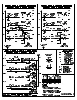
Страница 37: ...switch MD Grill microswitch MG Rotisserie MP Door microswitch N Neutral P Timer Programmer P Timer Clock PE Electric hotplate WIRING DIAGRAMS Keys R1 Upper heating element R2 Lower heating element R3 Grill heating element R4 Circular heating element R5 Barbecue heating element R6 Fryer heating element RE Energy regulator S1 Oven warning light S2 Mains power warning light S3 Grill warning light S4 ...

Страница 38: ...11 P2 P3 5 C 2 1 3 4 P1 1 2 4 3 55 44 33 22 33 PE 1 2 4 3 55 44 33 K14 K15 45 AA SP 66 MA MA MA MA MA 11 Models H392 H391 SP AA 66 11 11 MA MA MA RE 00 S5 MA MA N F M 11 66 P2 4 00 P1 2 00 R5 K1 K15 K16 45 WIRING DIAGRAMS only models with electric barbecue ...

Страница 39: ...Troubleshooting Guide PROBLEM The flame is not uniform The flame changes sud denly To light the burners keep the ignition knob pressed for longer After ignition the flame goes out The grill in the burner area has changed color Electrical operation is gene rally disturbed The electric ignition no longer works The burner lids are dirty POSSIBLE CAUSE Gas regulation not suitable The burner parts are ...

Страница 40: ...40 ...

Страница 41: ...NOTES ...

Страница 42: ......

Страница 43: ......

Страница 44: ......

Отзывы: