


ifm Vision Assistant O3M
172
15.12.3 "Analogue output" module
The "Analogue output" module transfers the numerical results from the logic editor to the connected
peripherals . A maximum of 20 numerical outputs are available . The "in1" input processes numerical
values or vectors .
The results are available at the following interfaces:
● Ethernet (UDP) (→ „16.3.1 Ethernet (UDP)“)
● CAN (J1939, CANOpen) (→ „16.3.2 CAN (J1939, CANOpen)“)
The numerical results are scaled to 0 . .1 when using the CAN interface . The scaled results
can be transferred directly to a physical analogue output on the receiver side (e .g . CAN
control) .
Thanks to the scaling it is possible to implement uniform standard programming regardless of
the functions of the device .
The bandwidth of the CAN interface is limited . Only the analogue outputs 0 . . .5 can be
transferred via the CAN interface .
within the 2D overlay (→ „11.2.1 Add text“)
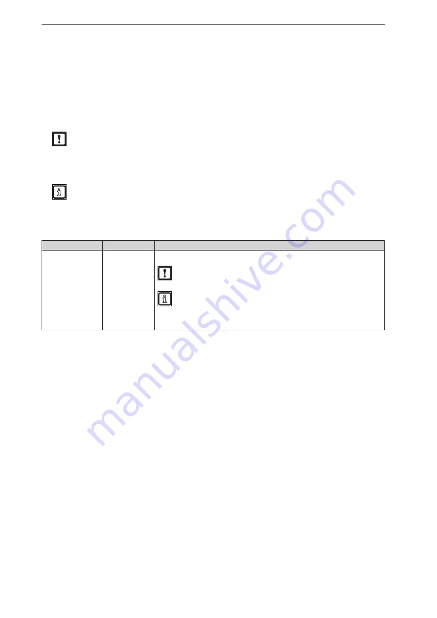
The "Analogue output" module has the following setting:
Setting
Data type
Description
Index
Numerical
You can use single indices or multiple indexes simultaneously (vectors) .
Duplicate addresses lead to an undefined state at the output .
►
Assign each address only once .
When using vectors at the "in1" input: If only one index is set, this index is used
as the start index .
Example: A vector with 8 binary values is present at input "in1" and index "3"
is set . Thus, the start index is "3" . The 8 numerical values are assigned to the
analogue outputs "3 . .10" .


