background image

Hangzhou IECHO Science & Technology Co., Ltd.

14

Steps for usage:

(1) Preparation (including installing the blade, setting the spindle speed, cutting
speed and other parameters);

(2) Edit cutting data in iBrightcut software and send it to Cutterserver.

(3) Place the material, turn on the suction and fix it;

(4) Turn on the power of the vacuum cleaner and start cutting

.

7.1. Power ON

When the knob switch is turned ON, the power of the router is turned on, and
the power indicator light is on.

Figure. 20

Note: when using emergency stop function, before turning on router power,
please turn on machine power firstly, otherwise the drive will report an error.

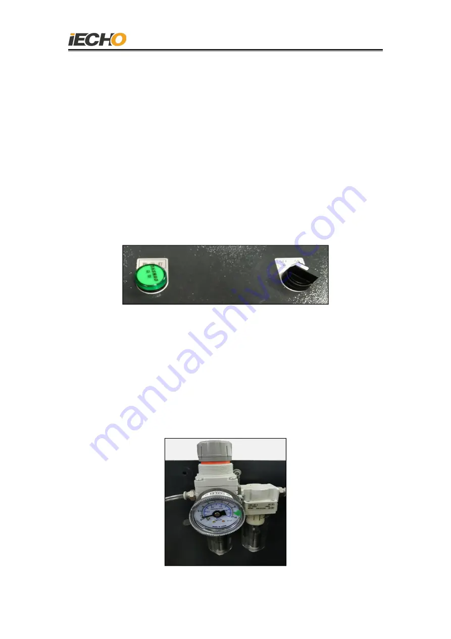
7.2. Cooling air pressure checking

Before starting the machine, please turn on the air source and check the air

pressure. The minimum air pressure required for router 0.04MPa. Too low or too
high air pressure will damage the spindle.

Figure. 21

Содержание 450W

Страница 1: ...Hangzhou IECHO Science Technology Co Ltd 1 450W Router User Manual Hangzhou IECHO Science Technology Co Ltd ...

Страница 2: ...bugging 7 6 1 Driver initialization 7 6 2 Spindle running in 10 6 3 Communication settings between Router and computer 11 6 4 Spindle rotating direction confirmation 13 7 Router operation 13 7 1 Power on 14 7 2 Cooling air pressure inspection 14 7 3 Blade installation 15 7 4 Router parameter setting 15 7 5 Communication serial port settings 16 7 6 Knife cutting depth setting 16 7 7 Router rotating...

Страница 3: ...dle Router controller vacuum cleaner dust suction pipeline air cooling pipeline and other components As shown in Figure 1 for the connection diagram of the main parts of the milling system the milling tool is installed on the universal head and it is connected with the driver in the router control box through a flexible cable A milling system suction device is installed on the universal head and t...

Страница 4: ...ure 1 Connection Diagram of Router Parts 1 Cutting head 6 Router hose holder 2 Milling tool 7 Router controlling box 3 Dust suction pipeline 8 Dust cleaner 4 Driver cable 9 Power Indicator 5 Air cooling pipeline 10 Power switch 9 1 2 6 7 8 10 3 4 5 ...

Страница 5: ...0 04MPa Collet maxɸ5 0mm 5 Essential of Router Installation 5 1 Installation of the suction pipe bracket of the cutting head Remove the two original M3 3 countersunk head screws on the side of the cutting head cover and use M3 6 countersunk screws to fix the suction tube bracket on the cutting head Replace the two M3 3 countersunk head screws of the cutting head cover with M3 6 countersunk head sc...

Страница 6: ...necting the milling spindle and the drive cable please check whether there is anything in the plug and clean then insert the plug straight to the end after aligning the position When you hear a click sound it means that the plug is locked Then insert a 4 0mm air pipe and connect with the milling spindle Figure 3 The connection between the milling spindle and the cable air pipe ...

Страница 7: ...able into milling tool control box connection Figure 5 Connect the emergency stop cable to the electrical box of the machine 5 4 Gas source connection Use a 6mm intake pipe to connect the intake end of the filter The cooling air is controlled by a solenoid valve When the milling tool is powered on the solenoid valve opens automatically The output interface is on the outside of the milling tool con...

Страница 8: ...ta cable to the USB port of the computer Figure 7 USB communication cable connection 6 Milling tool debugging Note The 0 04MPa clean air source must be connected before the spindle runs 6 1 Driver initialization The driver initialization is completed when the device is debugged first time in the factory and SycoDrive software must be installed before the operation Https www sycotec eu en about syc...

Страница 9: ...8 Figure 8 Start the SycoDrive software as shown in Pic 9 a green light is displayed in the lower left corner of the page indicating that the drive is successfully connected to the computer Figure 9 Green means connected System status display ...

Страница 10: ...The 450 milling spindle model is 4033 AC and the maximum speed is set to 100000rpm Click the Load motor type button on the page The following prompt pops up indicating that the import was successful Figure 11 2 After setting the above parameters click the Save on inverter button at the bottom right corner of the main page Figure 12 ...

Страница 11: ... has done the initial run in before the product leaves the factory However if the spindle is out of service for a long time more than 3 months it must be re run in before using it again Operation method Start the Sycodrive software on the SPINDLE RUN IN page first set the spindle model 4033 AC 100000rpm in the Spindle run in control column then select the running in method as Downtime 3 months and...

Страница 12: ...indow pops up indicating that the running in is complete Figure 16 6 3 Communication settings between milling tool and computer After the USB communication line is connected WINDOWS will automatically discover the hardware and automatically generate a serial port as shown in the picture USB Serial Port COM3 will appear in the device manager and the serial port number will be randomly generated ...

Страница 13: ... and the serial port number will be generated after installation There is no need to set the serial port number when connecting the milling tool it can be automatically connected after startup When using the CutterServer software the milling tool communication serial port must be set first Note Sycodrive software and CutterServer software cannot be connected at the same time Before running one of ...

Страница 14: ... figure If it is not correct please check if the cable connected properly The software can not change the rotation direction setting Figure 19 7 The use of router 450W Router software version requirements DSP program version DSP2 2 8 6A180903M and above CutterServer software version V4 2019 9 4 511 and above iBrightCut software version V4 2020 4 3 2373 and above Router rotation direction ...

Страница 15: ...nd start cutting 7 1 Power ON When the knob switch is turned ON the power of the router is turned on and the power indicator light is on Figure 20 Note when using emergency stop function before turning on router power please turn on machine power firstly otherwise the drive will report an error 7 2 Cooling air pressure checking Before starting the machine please turn on the air source and check th...

Страница 16: ...ert the router blade into the blade collet keep a distance of about 1mm between the cutting edge and the collet 4 Use 8mm and 12mm wrenches to tighten the nuts Figure 22 Note Please follow the blade installation steps above The wrong installation sequence may cause damage to the collet 7 4 Router parameter setting In the Cutterserver software parameter table the tool name is selected as MILL450 th...

Страница 17: ...tion to set the milling router serial port Figure 24 7 6 Set knife depth Select the milling router icon and click the manual tool setting icon to open the manual tool setting window Press the down arrow on the keyboard and the milling router will start to fall Stop when it is adjusted to the upper surface of the cutting mat click OK to complete the knife setting ...

Страница 18: ...sed and dustproof when working and is permanently lubricated Any act of adding grease and using cleaning solvents will damage the spindle The tapered surface of the chuck must be kept clean and free from scratches otherwise the accuracy of the tapered surface of the front end of the spindle rotor will be changed resulting in the inability to lock the tool resulting in failures such as tool drop or...

Страница 19: ...shaft Please use the matching professional tools for disassembly and assembly of the chuck if the bearing is damaged due to man made reasons no warranty treatment will be done if there is any problem with the spindle please do not disassemble and install it privately 9 Daily maintenance of milling router Check item Check content Require Water separator 1 Check the installation 2 Check the standing...

Страница 20: ...2 Check whether the pipeline is flattened 3 Check whether the pipeline is blocked 4 Check whether the debris in the vacuum cleaner bucket is full 1 Confirm that the pipeline is installed in place 2 Straighten out the pipeline do not flatten 3 Do not block the blockage can be taken out by shaking the suction tube 4 Clean up in time when the vacuum cleaner bucket is full 10 Milling router driver ala...

Страница 21: ...Blink 2 times Transfer parameters from micro SD card successfully Blink 2 times Blink 2 times Failed to transfer parameters from micro SD card OFF Blink 3 times Transfer parameters to micro SD card successfully Blink 3 times Blink 3 times Failed to transfer parameters to micro SD card 10 2 Warning codes and error codes When the drive alarms you can read more detailed alarm information in the SycoD...

Страница 22: ...during operation Warning code Fault Reason Solution 1 Motor current exceeds current limit The motor load is too high the parameter acceleration ramp is too short or the start current is too large If possible reduce the load and modify the parameters 8 Exceed the I t threshold Load is too high Reduce the load check the parameters I t time and I t threshold ...

Страница 23: ...bad SD card or the parameter file on the SD card is incomplete or does not exist Use a complete parameter file parameter import and a complete SD card 27 Generator running The motor runs on the inverter and stops Wait until the motor is stationary 28 Comparator s own error test Internal fault If the fault still exists after the power is turned off and on send the inverter for repair 45 Watchdog re...

Страница 24: ...ng code Fault Reason Solution 2 STO interrupt STO port open Check STO port 3 Motor ground leakage Short circuit of motor or power cord Replace or repair the motor Check the power cord 4 Radiator temperature High inverter Inverter overload Insufficient cooling Reduce load Check the output current 5 Inverter failure during self test Performance component failed Switch twice If the fault still exists...

Страница 25: ...celeration ramp is too low Test the power supply voltage and power connection Check the parameter Deceleration ramp 17 Motor connecting screw No motor connection or motor phase loss Check the motor connection Adjust the parameter motor type 29 Error during parameter import export Digital configuration error DIN6 and DIN6 input Check the signal values at DIN5 and DIN6 and their configuration 53 Sho...

Страница 26: ... error is reported when the milling cutter is turned on Possible cause The emergency stop line is disconnected the cutting equipment is not turned on Solution Check the emergency stop line and eliminate the line problem first turn on the power of the machine then turn on the power of the milling cutter 3 The milling cutter is disconnected Possible cause The power of the milling cutter is turned of...

Страница 27: ...he lock catch cannot be installed in the positioning rod Possible reason The direction of the tool holder of the machine head needs to be modified non tool direction parameter Solution Modify the machine parameters the angle between the knife and X positive direction under the tool holder Figure 28 ...

Страница 28: ... as IECHO IECHO does not make any guarantee for this technical document and IECHO is not responsible for any misunderstandings that may be caused by users of this technical document IECHO reserves the right of final interpretation for any discrepancies between the product purchased by the user and this technical document IECHO National Free Service Hotline 400 119 1990 ...

Отзывы: