background image


 FINGER006 SERIES QUICK INSTALLATION GUIDE 


10 

5. Installation of the Product 

* As long as there is not mention, contents below are applied to FINGER006, IP-FINGER006, FINGER006SR equally. 

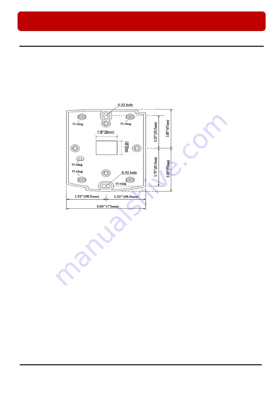
5.1 Template 


Tear off the Template page at the back of this manual and use the Template to drill two 6-32 holes and one ½” 
hole on the proper location of the wall to mount the Wall Mount bracket as shown below.   

      (If the gang box is installed on the wall, skip this step.)   


  Using 2 screws, install wall mount to the wall.   


  Insert 5 O-Rings to the Wall Mount as indicated, then run the cable from the main unit through     


the center hole and snap in place the main unit to Wall Mount. Make sure that the main unit is 
secure locked in place with Wall Mount. 


Caution


Before mounting the Star FINGER006 / iPASS IP-FINGER006 / IDTECK FINGER006SR unit to the Wall Mount 
bracket, an operational test of the unit should be completed, because the locking pins will lock the unit to the 
Wall Mount.   
Removing the unit from the Wall Mount bracket after it has been snapped in place may cause damage to the 
bracket and prevent reattachment. 


Содержание Star FINGER006

Страница 1: ...Quick Installation Guide Fingerprint Identification Proximity PIN Reader...

Страница 2: ...ck Never spill liquid of any kind on the product 7 Never disassemble this product by yourself take the unit to a qualified service center whenever service or repair is required Opening or removing the...

Страница 3: ...power supply The green LED turns on if access has granted The orange LED turns on if access has failed Finger Print Scanner When users put their finger on the scanner white light will turn on 16 Nume...

Страница 4: ...han 2 seconds Refer to 8 2 System Initialization for more details Communication Display LED 3 4 yellow green LED will twinkle during RS232 RS422 and TCP IP communication If the LAN is connected normal...

Страница 5: ...ed Stripe OK Input OK Input Green Error Input Error Input Green with White Stripe EXTERNAL READER PORT CON5 Wiegand Data0 Wiegand DATA0 Input Pink Wiegand Data1 Wiegand DATA1 Input Cyan OUTPUT CON5 Wi...

Страница 6: ...TX TX Gray RS422 RX RX Blue RS422 RX RX Brown TCP IP Communication CON6 TCP IP Communication Optional 8PIN connector module 3 4 TCP IP Module Option The Finger006 is able to use TCP IP Communication A...

Страница 7: ...ols and readily available communications wires This section provides information about wiring wire runs and other information to make the installation quick and easy 4 1 Check Points before Installati...

Страница 8: ...portion of signal is reflected back into the transmission line The decision whether or not to use termination resistors should be based on the cable length and data rate used by the communication syst...

Страница 9: ...of shield wires to the grounding system in this case there will be a current flow through the shield wire when the voltage level of both ends of shield wire is not equal and this current flow will cre...

Страница 10: ...tep Using 2 screws install wall mount to the wall Insert 5 O Rings to the Wall Mount as indicated then run the cable from the main unit through the center hole and snap in place the main unit to Wall...

Страница 11: ...Board ID Besides the method described above there is one more method for system initialization which is by entering setting menu In this case all setting values will be cleared except Board ID If you...

Страница 12: ...ctor Serial communication connector female is required to connect the FINGER006 to a host computer via RS232 communication Please follow the instructions Connect RS232 TX port of FINGER006 to the pin...

Страница 13: ...other FINGER006 Connect RS422 RX of one FINGER006 to RS422 RX of another FINGER006 Connect RS422 RX of one FINGER006 to RS422 RX of another FINGER006 Second you have to connect one of RS422 port of FI...

Страница 14: ...INGER006 unit Then the LCD will first display Initialize OK 1 Yes 0 No Press 1 key if you want to initialize the system or 0 to cancel the initialization procedure After all the initialization process...

Страница 15: ...the current date and time To adjust the time date setting press ENT then enter 15 Digits in a YYYYMMDDhhmmssW format and then enter ENT again to confirm NOTE For the days of the week W 1 Sun 2 Mon 3 T...

Страница 16: ...from OK output wire for 500ms Default Registered Card Reading When a registered card or PIN is read the door will open for 3 seconds Defaults with the GREEN LED on Alarms Unregistered Password Finger...

Страница 17: ...FINGER006 SERIES QUICK INSTALLATION GUIDE 17 9 Template...

Отзывы: