MSD-62 Series User’s Guide
71
9.4.10 Background color
Menu Top
→
OUTPUT TIMING
→
BACKGROUND COLOR
Setting for Each output channel
Setting for R / G / B:0 to 255 [Default] R / G / B: 0 (black)
You can set the background color of output video.
If you set “LINK” to ”ON”, only the setting for ”R” can be set, and “G” and “B” track the setting of “R”.
9.4.11 Test pattern
Menu Top
→
OUTPUT TIMING
→
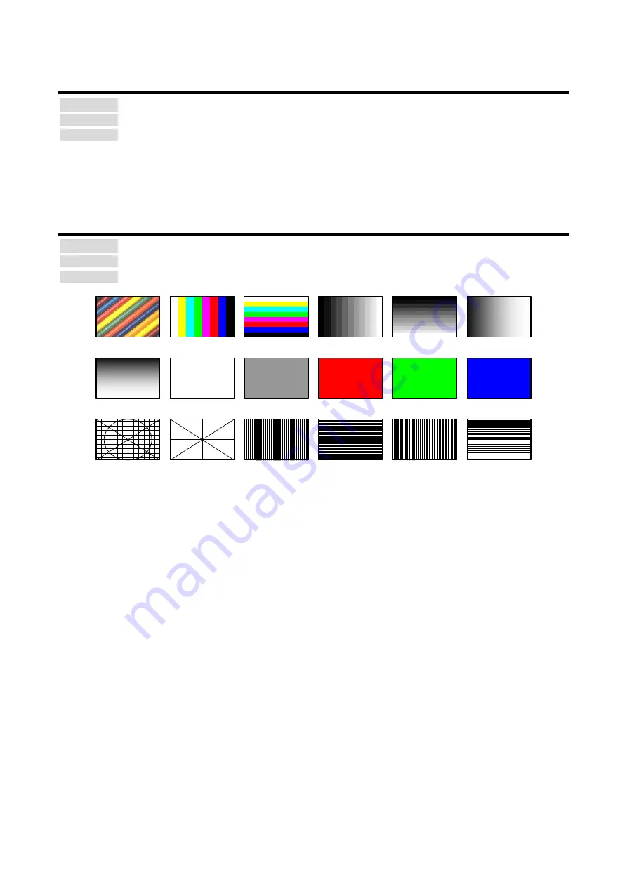
TEST PATTERN
Setting for Each output channel
Setting for [Fig. 9.7] Test pattern
VERTICAL RAMP
OFF [Default]
50% WHITE
RASTER
V-COLOR BAR
V-GRAY SCALE
RED RASTER
GREEN RASTER
BLUE RASTER
100% WHITE
RASTER
CROSS HATCH OUTPUT FRAME
VERTICAL
STRIPE
HORIZONTAL
STRIPE
VERTICAL
ZEBRA
H-COLOR BAR
H-GRAY SCALE
HORIZONTAL
RAMP
HORIZONTAL
ZEBRA
[Fig. 9.7] Test pattern
You can activate the MSD’s internal test pattern generator and direct its signal to each output connector.
While active, the test pattern will override any other signal that has been switched to that particular output
connector.
All settings of
will be invalid while a test pattern is displayed.
“OUTPUT FRAME”: Select this pattern if part of image is not displayed on the sink device.
Settings of “
” and
in the output side will be adjusted in order to
display the test pattern on full screen.
For test patterns other than “OUTPUT FRAME”: video is output on full screen with the resolution set in “
will be invalid.
You can use the arrow keys (
▼
,
▲
,
▼
) to scroll through the available patterns “COLOR BAR”, ”GRAY
SCALE”, ”RAMP”, and ”ZEBRA” by using. The scroll speed can be set by 3 pixels per frame up to 30 pixels
per frame with
▲
and
▼
keys. You can check the residual image (resolution of moving picture) by
displaying and scrolling the “ZEBRA” pattern.
Note:
If combination mode is set (P.72), any test pattern cannot be output.


