5 HG1P
1-94
MICRO/I Hardware Manual
●
HG1P Debug Cable (HG9Z-PX12)
This cable is the debug cable. Use this cable only for debugging.
■
Cable Specification
■
Outline Drawing
■
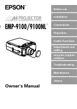
Sectional View
■
Wiring Table
Structure
Double shield cable
Configuration
AWG25 x 2 Pair
AWG23 x 5 Cores
Conductor
Configuration
40N/0.08mm(Pair), 60N/0.08mm(Cores)
Insulator
Material
PVC
Thickness
0.16mm(Pair), 0.145mm(Cores)
Outer Diameter
0.9mm(Pair), 1.0mm(Cores)
Sheath
Outer Diameter
7.0 mm
Cable Length 2m
Stripped Wires
Shield
White Black
Black Red
Green
Orange
Blue
Brown
Yellow
Shield
Sheath
Wire pair 2
Single wire 1
Single wire 5
Single wire 4
Single wire 3
Single wire 2
Wire pair 1
No.
Name
Function
Cable Color
1
RDA+/TP1+ Receive Data (+)
Wire pair 1 : Black
2
RDB-/TP1- Receive Data (-)
Wire pair 1 : Red
3
SDA+/TP0+ Send Data (+)
Wire pair 2 : Black
4
SDB-/TP0- Send Data (-)
Wire pair 2 : White
5
FG
Frame Ground
Single wire 1 : Green
6
SG
Communication Signal Ground
Single wire 2 : Yellow
7
DC24V+
Main unit 24V DC Power Supply (+)
Single wire 3 : Brown
8
NC
-
Single wire 4 : Blue
9
DC24V-
Main unit 24V DC Power Supply (-)
Single wire 5 : Orange