I-7530, I-7530A, I-7565, I-7530-FT, tM-7530, tM-7530A, tM-7565 User Manual Version 1.6
Page:
99
Copyright © 2018 ICP DAS Co., Ltd. All Rights Reserved E-mail: [email protected]
Communication description:
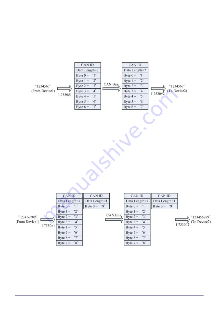
For example, if device 1 sends 7 bytes of data ""1234567"" to I-7530 module #1, I-
7530 module #1 then forwards it to I-7530 module #2, and finally I-7530 Module #2 will
send to the COM port of Device 2, and Device 2 will receive the data ""1234567"".
The CAN ID in the above picture needs the user to set a fixed CAN ID, and the
"Fixed CAN ID" parameter in the setting screen. If the CAN specification selected by the
user is CAN 2.0A and the CAN ID is 11-bit ID, the range is 000~7FF. If the CAN
specification selected by the user is CAN 2.0B and the CAN ID is 29 -bit ID, the range is
0000000~1FFFFFFF.
In addition, since a CAN message can only contain 8 bytes of data, if device 1
sends 9 bytes of data "123456789" to I-7530 module #1, I-7530 module #1 will divide
the 9 bytes into 2 CAN messages and forwarded to I -7530#2. Finally, I-7530 module #2
merges the 2 CAN messages back to "123456789" and forwards them to the COM port
of device 2. Therefore, device 2 will receive the data of "123456789".
Note: If the user uses 115200bps in the CAN RS -232 communication port, it is
recommended to configure the baud rate of the CAN side of the CAN converter
to be close to the same baud rate, such as 125Kbps. When you are using the
pair connection mode, the appropriate baud rate should be below 125Kbps.


