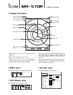
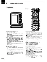
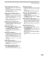

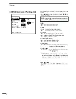

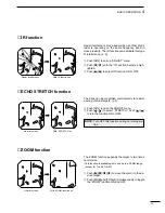


PANEL DESCRIPTION
2
2
■
Front panel
MARINE RADAR
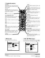
q
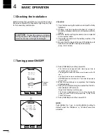
POWER SWITCH [POWER] (p. 10)
Turns power ON and OFF.
• The standby screen appears for 90 sec. while warming
up the magnetron.
• The initial screen appears with a beep after the power
has been turned ON.
w
EBL1 (VRM1) SWITCH [EBL1 (VRM1)] (pgs. 16–18)
Push to display the electronic bearing line 1 (EBL1)
and the variable range marker 1 (VRM1) on the
cross line cursor position from own ship.
• EBL1 bearing and VRM1 distance are displayed, in the
bottom window.
• When EBL1 and VRM1 are displayed, the beginning of
EBL2 appears at own ship or the intersection point of
EBL1 and VRM1.
e
ALARM SWITCH [ALM] (p. 19)
Push [ALM] to toggle the alarm function ON and
OFF.
Push and hold [ALM] for 0.5 sec. to enter the alarm
area setting condition.
• Push
[
]/
[
]/
[
]
/[
]
key to move the cross cursor to
the zone
starting point, then push [ALM] for 0.5 sec. The
starting ring of the zone is created. Then push
[
]/
[
]/
[
]
/[
]
to fix the finish point, the desired alarm zone
will automatically form.
r
MAN OVERBOARD [MOB]
Push to mark the man overboard point on the
screen. In the case of when a crew member falls
overboard, push [MOB] to display the MOB marker
(
) on the screen.
• MOB readout shows the bearing, distance and esti-
mated time to the MOB point with current speed.
• Push and hold [MOB] for 0.5 sec. to cancel the function.
• Position and bearing data are necessary.
• External data is required for screen display information.
(p.38).
t
RANGE UP/ DOWN SWITCH [+/ –] (p. 16)
Push [+] to increase the screen range.
Push [–] to decrease the screen range.
y
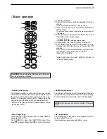
UP, DOWN, LEFT, RIGHT KEY
[UP][DOWN][RIGHT][LEFT]
Set the cross line cursor, alarm area, EPA target,
etc. according to the switch pushed.
Use the
[
]/
[
]
key to select menu item and
[
]
/[
]
key to set the item.
Using the
[
]
-
[
]
/[
]
or
[
]
-
[
]
/[
]
key combina-
tion allows you to move the cross line cursor to the
upper (or lower) left or right.
u
ADJUST MENU [ADJ] (p. 6)
Push [ADJ] to show the adjust menu on the display.
• Adjustable items; TUNE, GAIN, SEA, RAIN, IR, ES,
PULSE length.
!8
!1
!7
!5
!3
o
i
t
r
e
w
q
u
y
!0
!2
!4
!6
Control panel
Содержание MR-570R
Страница 3: ...INSTRUCTION MANUAL MARINE RADAR MR 570R ...
Страница 36: ...30 9 INSTALLATION AND CONNECTIONS THIS PAGE IS INTENDED TO BE BLANK ...
Страница 45: ...15 39 TEMPLATE 160 mm 6 5 16 91 mm 3 19 32 EX 2473 TEMPLATE ...
Страница 46: ...40 ...
Страница 47: ...Ship bow direction Radius is 6 mm 1 4 in EX 2474 Scanner unit template 45 5 mm 125 32 in ...
Страница 48: ...90 5 mm 39 16 in 90 5 mm 39 16 in 150 5 mm 515 16 in 37 41 15 TEMPLATE ...
Страница 49: ...1 1 32 Kamiminami Hirano ku Osaka 547 0003 Japan A 6014H 1EX q Printed in Japan 2001 Icom Inc ...


