background image

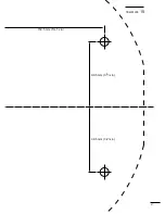
90.5 mm (3

9

16

 in)

90.5 mm (3

9

16

 in)

150.5 mm (5

15

16

 in)

37

41

15

TEMPLATE

Содержание MR-570R

Страница 1: ... data with 0183 format is necessary 4 This area may differ depending on DATA DISP selection in the FUNCTION menu Nautical miles NM and kilometres KM can be selected in the INT SETTING menu as the dis tance unit 5 North up N UP and Course up C UP screens require ex ternal bearing data True Motion TM screen requires bear ing data and LOG or position data BRILL menu Push BRILL to select the brillianc...

Страница 2: ...ys to select the items and push keys to change the setting ZOOM Push MOB and TRAILS simultaneously to toggle the ZOOM function ON and OFF TRAILS Toggles the trail function ON and OFF OFF CENT Push ALM and MODE simultaneously to turn the OFF CENTER function ON or OFF MODE Push to select one of Head up H UP Course up C UP North up N UP or True motion TM screens PI Push EBL1 and EBL2 simultaneously t...

Страница 3: ...INSTRUCTION MANUAL MARINE RADAR MR 570R ...

Страница 4: ...C 928 1 t NMEA connector cover 2 y Self tapping screws 5 x 30 4 u Spring washers M5 4 i Flat washers M5 4 o Mounting spacer 4 0 Mounting rubbers 4 EX 2474 Scanner unit Qty q System cable OPC 1075 10 m 1 w Installation bolts M10 x 50 4 e Installation bolts M10 x 25 4 r Installation nuts M10 4 t Flat washers M10 4 y Spring washers M10 4 SUPPLIED ACCESSORIES and Icom Inc are registered trademarks of ...

Страница 5: ...trong solvents such as benzene or al cohol for cleaning the radar as they may damage the surfaces PRECAUTIONS FOREWORD Thank you for purchasing ICOM s MR 570R MARINE RADAR The radar is designed especially for fishing boats It has powerful transmission power a 5 7 inch LCD dis play and many other advanced features If you have any questions regarding the operation of the radar contact your nearest a...

Страница 6: ... setting 19 7 EPA Electronic Plotting Aid 20 22 EPA Electronic Plotting Aid 20 EPA menu setting 20 EPA operation 21 Correct the target 21 Clear the target 22 Plotting marks 22 Course and speed vector 22 Plots 22 8 BASIC RADAR THEORY 23 25 Side lobe echoes 23 Indirect echoes 23 Multiple echoes 24 Minimum range 24 Blind and Shadow sectors 25 Target resolution 25 9 INSTALLATION AND CONNECTIONS 26 30 ...

Страница 7: ...y cause electrocution and death even an electric shock of only 100 volts may be fatal PREVENTION OF ELECTRIC SHOCK FOR QUALIFIED ELECTRONIC TECHNICIANS ONLY To prevent such accidents turn OFF the power source and do not reach inside the unit until you have q Discharged the capacitors by disconnecting the power cable from the power source for 5 min w Checked that no electric charges remain inside t...

Страница 8: ...eated Then push to fix the finish point the desired alarm zone will automatically form r MAN OVERBOARD MOB Push to mark the man overboard point on the screen In the case of when a crew member falls overboard push MOB to display the MOB marker on the screen MOB readout shows the bearing distance and esti mated time to the MOB point with current speed Push and hold MOB for 0 5 sec to cancel the func...

Страница 9: ...t available at 1 8 3 4 and 32 NM or above ranges 3 TRAILS SWITCH TRAILS p 14 Push to toggle the trail function ON and OFF This is useful for watching other ship s tracks approx rela tive speed etc Trail Time can be set in FUNCTION menu 4 OFF CENTER FUNCTION OFF CENT p 12 Push ALM and MODE simultaneously to turn the OFF CENTER function ON or OFF This function is not available at 32 NM or above rang...

Страница 10: ...VRM1 EBL2 VRM2 READOUTS pgs 16 18 Shows the bearing of the displayed Electronic Bear ing Lines EBL and the distance of the displayed Variable Range Markers VRM Nautical miles NM and kilometres KM can be se lected in the INT SETTING menu as the distance unit 7 HEADING INDICATOR Shows the heading bearing readout The HDG readout indicates the bow of the ship s bearing in a clockwise direction from no...

Страница 11: ... information p 38 When CURS or SHIP is selected 8 POSITION CURSOR READOUT p 15 Shows your own ship or cursor latitude and longi tude readout when external NMEA data with 0183 format is connected Select CURS or SHIP in the FUNCTION menu External data is required for screen display information p 38 When WPT is selected 9WAYPOINT READOUTS p 15 Shows the bearing and distance to the waypoint re ceived ...

Страница 12: ...tead of the screen display when first transmitting after turning the power on The unit also re tunes in some cases When activating the manual tuning slider push to adjust desired tuning level GAIN CONTROL GAIN p 11 Adjusts the receiver amplifier gain Increased gain may increase screen noise SEA CLUTTER CONTROL SEA p 12 This function serves to eliminate echoes from the waves at close range Reduces ...

Страница 13: ...e bottom left OFF Display the bearing distance and time on the screen ON Display the Latitude and Longitude on the screen CURS WPT AND MOB WPT OFF For not displaying the way point mark on the screen ON To display the way point mark on the screen OWN VECT OFF For not displaying the own ship vector ON To display your own ship s vector TRAIL TIME 15S 30S 1M 3M 6M 15M 30M or Select the plot interval a...

Страница 14: ... alarm function ON CPA LIMIT 0 1 to 50 0 NM Set the CPA Closest Point of Ap proach limit with keys TCPA LIMIT 1 to 60 MIN Set the TCPA Time to CPA limit time with keys CPA TCPA Closest Point of Approach and Time to Clos est Point of Approach limit is defined by the observer to give a warning when a target or targets are close to within those limits from your own ship INT SETTING Push to open the I...

Страница 15: ...a incorrect variation data may entered p 38 MANUAL Revise magnetic variation manually Push to select MANUAL then push Set the revised value with Push or MENU key to abort the menu BRG INPUT NMEA NMEA0183 bearing data format N 1 N 1 data format AUX Other format SPD INPUT GPS Use the GPS NMEA speed data LOG Use the speed sensor data TX INH START 0 to 359 Push key to enter the start point of the TX i...

Страница 16: ...on inside the scanner unit warms up for 90 sec The firmware s revision number appears POWER does not function for 2 sec after the power is turned OFF w When the countdown is completed the Standby screen appears e Push TX to start scanning and select the Plan Po sition Indicator PPI screen Targets and heading marker appear The screen appears approx 5 sec after turning the power on when AUTO is sele...

Страница 17: ... set the SEA to minimum y Push MODE to select one of HUP Head up CUP Course up NUP North up or True motion TM screens C UP N UP or TM can be selected only when bear ing position or speed data are connected See p 26 for details Select each item then push ADJ for 0 5 sec to use auto setting mode Basic operation y w e q r Brilliance adjustment The intensity of the screen can be adjusted When you requ...

Страница 18: ...ution and careful adjustment are necessary when using the SEA control Small objects may not be displayed on the screen when strong echoes from the rain or the island within 1 NM while automatic SEA function is activating Adjust SEA control Echos from sea waves Adjust RAIN control Small echos OFF CENTER function The scanning area can be shifted in a desired direc tion and can be enlarged partially ...

Страница 19: ...ction The blips can be magnified electronically for easier viewing of small targets p 6 q Push ADJ to open the ADJUST menu w Push to select STRETCH Push to turn the function ON or OFF ZOOM function The ZOOM function expands the target to two times normal size This function is available within and up to a 24 NM range except for 1 8 and 3 4 NM q Push to move the cursor to the de sired target w Push ...

Страница 20: ... fixed on 10 rotations For example when 1 min is selected the scanner ro tates 10 revolutions then stops for 1 min and then re peats this sequence while the power save function is activated Setting the scanning standby time q Push MENU to call up the FUNCTION menu w Push DOWN until the SAVE TIME section be comes highlighted e Push to select standby time 1 6 15 and 30 min are available r Push MENU ...

Страница 21: ...nify the blips for easier viewing of small targets the long pulse and echo stretch p 11 functions are available When the long pulse is used in the 3 4 to 2 NM range this function magnifies target echoes to the backward direction of the target Pulse selection q Push ADJ to call up the Adjust menu p 6 w Push until the PULSE section becomes highlighted e Push to select the long pulse r Push ADJ to ex...

Страница 22: ...everal times to move the cross line cursor on the target w Push EBL1 VRM1 to display EBL1 and VRM1 w Push EBL1 VRM1 again to cancel EBL1 and VRM1 S0672 EBL VRM1 EBL VRM2 R R S0162 3 1 NM 2530 Fixed Ring Ring range readout T 1 296NM O 01 O 01 0 566NM TYPE DESCRIPTION RING Displays fixed rings Suitable for rough estimations from your own ship to any target VRM1 Displays a variable range marker Suit ...

Страница 23: ...u see p 7 Bearing data is required p 38 e Push several times to move the cross line cursor on the another target r Push EBL2 VRM2 to display the EBL2 and VRM2 The EBL2 and VRM2 readouts indicate the target bear ing and distance t Push EBL2 VRM2 once more to display the EBL2 and VRM2 from the intersection point of the VRM1 and EBL1 When the EBL2 VRM2 is pushed again the center of VRM2 appears at th...

Страница 24: ...RAILS p 12 ON then wait until the trail time count up reaches to the TRAIL TIME w Set VRM1 and EBL1 to a previously plotted target as described above e Set VRM2 and EBL2 to the current plotted position of the same target as described as above r The VRM2 readout is a measurement of target movement which can be converted into relative tar get speed For example when a 6 min trail time is selected mul...

Страница 25: ...n is turned ON The LCD display turns OFF When a target comes into the alarm zone an alarm sig nal is emitted the LCD display turns ON and the power save function is cancelled The unit has an alarm function to protect your ship from collisions If other ships or islands etc come into the pre programmed alarm zone the function alerts you with an alarm You can set the desired range and bearing for an ...

Страница 26: ... w Push LEFT to turn the EPA function ON e Push to select VECT push to select the vector type TRUE True vector The predicted true motion of a target as the result of your own ship s direction and speed input REL Relative vector The predicted movement of a target relative to your own ship r Push DOWN to select No DISP to select the tar get identification number type which appears at the right side ...

Страница 27: ...TCPA 4 25 Bearing Distance Course Speed Identification No Closest Point of Approach Time to Closest Point of Approach Vector time R T ALL CLR CORR Set menu CLR No 1 BRG 337 3 0 45 CSE CPA DIST 2 041NM SPD TCPA R Correct the target Correct the uncalculated target You can correct the uncalculated target by pushing the EPA until the progressing time reaches 30 sec q Push to move the cursor on the pro...

Страница 28: ...ted uncalculated mark Selected calculated mark Normal uncalculated mark Normal calculated mark CPA TCPA alarm mark The target is close to within a minimum range and time Alarm emit indicator Push EPA to can cel the alarm Clear the target You can clear the unnecessary target vector q Push EPA to display the EPA information screen w Push to select the desired target number e Push to select CLR to cl...

Страница 29: ...ting surface will appear on a different bearing from the direct true echo but the distance will be approximately the same for both Radar uses a form of electromagnetic radiation which like light can be reflected Because of this property some objects may cause false echoes on the screen where in fact no targets actually exist These echoes may appear if a large vessel bridge or tank is in proximity ...

Страница 30: ...um range is determined primarily by transmitter pulse length vertical beam width and height of the scanner unit The shorter the transmission time the quicker the return echoes can be received and their distance mea sured The ability to see targets very close to the ship is de creased if the scanner unit is mounted too high off the water because the bottom of the vertical beam of the scanner cuts o...

Страница 31: ...by the horizontal beam width and transmit pulse width Sometimes it is difficult to detect two targets which are separated by short dis tances or which are in the same direction Distance resolution When two targets are separated by more than the pulse width they appear as two echoes When two targets are not separated by more than the pulse width they appear as 1 echo Direction resolution When two t...

Страница 32: ...power source The radar is designed for connection to any power source if the voltage is 10 2 42 V DC so that a 12 24 or 32 V DC battery can be used without a DC DC con verter or any internal modifications DC power cable connection Connect the supplied DC power cable as shown in the diagram Ground connection To prevent electrical shocks and other problems ground the display unit through the GND ter...

Страница 33: ... subject to extreme heat cold vibrations or direct sunlight Mounting The stand supplied with the display unit allows dash board or overhead mounting q Hold the stand of the display unit up to the selected location and mark pilot holes for the 4 installation holes using the template The template is provide on p 43 w Drill 4 holes of 3 6 to 4 0 mm 5 32 in in diameter e Secure the stand with the self...

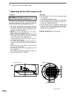
Страница 34: ...on the boat to obtain best performance with maximum range t If you install two or more radar in one boat install one above and one below y The mounting surface must be parallel with the boat s waterline u If the height is insufficient to install the scanner unit build a special frame for installation Mounting q Drill four holes of 12 mm 1 2 in in diameter using the template The template is provide...

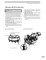
Страница 35: ...tem cable with the ferrite core at tached near the sealing connector Be sure to clamp it tightly i Connect the power cable black and red end to the power unit connector 2 Be sure to follow the fol lowing diagram carefully o Tighten the sealing nut then replace the radome cover over the scanner unit DO NOT stretch the system cable too much other wise miss contact of the connector may occur 0 Tighte...

Страница 36: ...30 9 INSTALLATION AND CONNECTIONS THIS PAGE IS INTENDED TO BE BLANK ...

Страница 37: ... 12 16 24 32 36 Choose the selectable screen range Other readouts OUTPUT VOLTAGE Shows the voltage level for the scanner unit from the display unit HV High voltage Shows the voltage level in the high voltage unit in the scanner unit MONITOR Shows the voltage level for checking the receiver unit operation HEATER Shows the heater current MG Shows the current level for the Magnetron TX TIME Shows the...

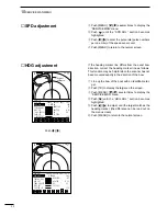
Страница 38: ...sh TX to display the target on the screen e Push MENU several times to display the SERVICE MAN menu rPush until the HDG ADJ section becomes highlighted tPush to adjust until the target matches the heading marker the difference can be read out on the menu screen y Push MENU to return to the normal screen Angle of difference SPD ADJ HDG ADJ TIMING ADJ MBS SET TUNE PRESET TUNE SET T METER SET ENGLISH...

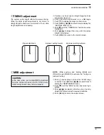
Страница 39: ... length adjustment is not correct a straight target is shown as a curved echo Thus cable length adjustment is necessary q Position your boat near a straight target such as breakwater wharf etc w Push several times to select 1 8 or 1 4 NM range e Push TX to display the target on the screen r Push MENU several times to display the SERVICE MAN menu tPush until the TIMING ADJ section becomes highlight...

Страница 40: ...o select TUNE PRESET tPush to adjust a comparatively weak echo for maximum definition yPush to select the T METER SET uPush to adjust a tuning level to show that it is at peak level see left iPush MENU to return to the normal screen DO NOT change the screen range before returning to the normal screen NOTE When returning to the normal screen the tun ing level indicator automatically adjusts to 85 o...

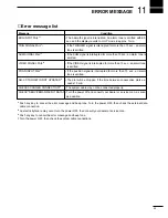
Страница 41: ...on signal is interrupted for more than 15 sec an alarm tone is emitted NO XX TARGET IS NOT UPDATED 3 The plot will be dropped if the time between consecutive plots ex ceeds 15 min CHECK SCANNER CONNECTION 4 The system cable may not be connected properly CHECK SERVICEMAN MENU DATA 2 Turn the power off and consult your dealer or service man as soon as possible Error message list 1 Push any key to ca...

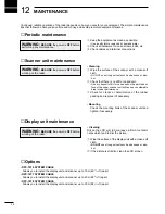
Страница 42: ... Use a soft cloth to remove dirt dust and water w Check all hardware for loose screws bolts etc e Check cables and terminal connections Scanner unit maintenance Display unit maintenance Cleaning Dirt on the LCD will in time leave a film of contami nates which tend to dim the picture q Wipe the surface of the display unit with a clean soft cloth DO NOT use strong solvents such as benzene or alco ho...

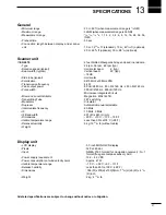
Страница 43: ...enclosed in a radome 24 rpm 36 rpm 48 rpm typ Horizontal beam 4 typ Vertical beam 22 typ 18 dB Horizontal 9410 MHz 30 MHz P0N 4 kW 80 nS 2880 Hz 80 nS 2160 Hz 250 nS 2160 Hz 350 nS 2160 Hz 900 nS 720 Hz Microwave Integrated Circuit Magnetron MAF1421B FET switching Circulator Automatic manual selectable 60 MHz 10 MHz 3 MHz 607 Ø x 243 H mm 25 C 70 C 13 F 158 F Less than 95 at 35 C 95 F 9 kg 1927 32...

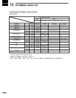
Страница 44: ...ed WAY POINT WPT Required RMC GGA or GLL WPL or BWC OWN VECTOR OG 1 Required RMC or VTG TW 1 Required LOG MOB MOB Required RMC GGA or GLL EPA OG 1 EPA Required RMC or VTG TW 1 EPA Required LOG VRM PI WPT MOB estimated time OG 1 RMC or VTG of arrival TW 1 LOG MAGNETIC VARIATION AUTO RMC or VTG 1 OG Over ground TW Through the water 2 NMEA1 and NMEA2 connectors See p 26 HDT HDM RMC GGA GLL VTG WPL an...

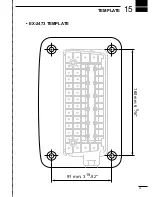
Страница 45: ...15 39 TEMPLATE 160 mm 6 5 16 91 mm 3 19 32 EX 2473 TEMPLATE ...

Страница 46: ...40 ...

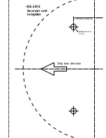
Страница 47: ...Ship bow direction Radius is 6 mm 1 4 in EX 2474 Scanner unit template 45 5 mm 125 32 in ...

Страница 48: ...90 5 mm 39 16 in 90 5 mm 39 16 in 150 5 mm 515 16 in 37 41 15 TEMPLATE ...

Страница 49: ...1 1 32 Kamiminami Hirano ku Osaka 547 0003 Japan A 6014H 1EX q Printed in Japan 2001 Icom Inc ...

Отзывы: