


11
4
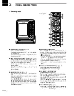
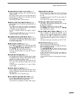
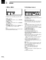
BASIC OPERATION
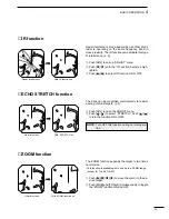
• Heading Line marker
The heading marker is a line that shows your ship’s
bow direction. (This marker will appear in the center of
the screen when the Head-up screen H UP is se-
lected.) The heading marker can be hidden when the
desired target is located under the heading marker.
• Push and hold [ADJ] and [MENU] simultaneously to hide
the heading marker.
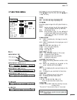
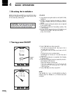
q
Turn the power ON.
w
Push [TX] after the countdown disappears from the
screen.
• See “Turning power ON/OFF” on page at left.
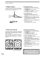
e
Push [+] or [–] key one or more times to select the
display range.
• The screen range readout shows the maximum range of
the screen.
r
Push [ADJ] then adjust the [GAIN]* to be on the
threshold of max. screen range.
• Increases the gain.
• Increased gain may increase screen noise.
t
Select [SEA]*, then set the [SEA]* to minimum.
y
Push [MODE] to select one of HUP (Head-up), CUP
(Course-up), NUP (North-up) or True motion TM
screens.
C UP, N UP or TM can be selected only when bear-
ing, position or speed data are connected.
(See p. 26 for details)
*Select each item ,then push [ADJ] for 0.5 sec. to
use auto setting mode.
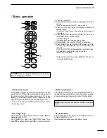
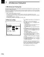
■
Basic operation
y
w
e
q
r
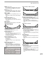
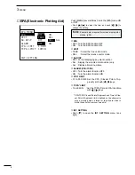
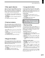
• Brilliance adjustment
The intensity of the screen can be adjusted. When you
require continuous operation, but not constant viewing,
a lower setting can increase the life of the backlight.
• Key illumination
The backlighting of the keys can be adjusted for con-
venient operation. (p. 6)
• Key illumination corresponds with [BRILL] control.
NOTE: High intensity will shorten the life of the back
light.
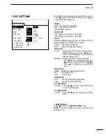
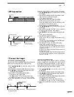
• Fixed range rings
The fixed range rings can be used for rough distance
measurement. (p. 14)
Push [MENU] to open the FUNCTION menu, then
push
[
]
to select RING. Push
[
]
to turn the ring ON.
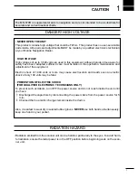
CAUTION:
When setting the [SEA] control to MAX posi-
tion, close targets are blanked.
Содержание MR-570R
Страница 3: ...INSTRUCTION MANUAL MARINE RADAR MR 570R ...
Страница 36: ...30 9 INSTALLATION AND CONNECTIONS THIS PAGE IS INTENDED TO BE BLANK ...
Страница 45: ...15 39 TEMPLATE 160 mm 6 5 16 91 mm 3 19 32 EX 2473 TEMPLATE ...
Страница 46: ...40 ...
Страница 47: ...Ship bow direction Radius is 6 mm 1 4 in EX 2474 Scanner unit template 45 5 mm 125 32 in ...
Страница 48: ...90 5 mm 39 16 in 90 5 mm 39 16 in 150 5 mm 515 16 in 37 41 15 TEMPLATE ...
Страница 49: ...1 1 32 Kamiminami Hirano ku Osaka 547 0003 Japan A 6014H 1EX q Printed in Japan 2001 Icom Inc ...


