■
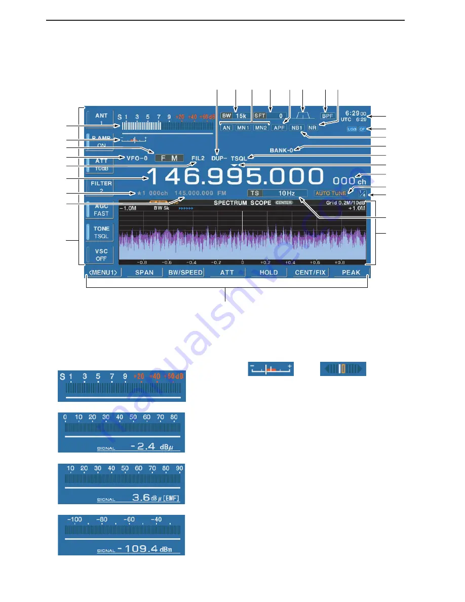
LCD display
q
RSSI METER
(p. 3-10)
Shows the received signal strength. Four meter
types, S, dBµ, dBµ(EMF) and dBm meters are se-
lectable.
w
CENTER METER
Shows that the received signal is tuned to its center
frequency for FM/WFM or FSK modes.
e
MODE INDICATOR
(p. 3-7)
Shows the selected receive mode.
r
VFO/MEMORY INDICATOR
(pgs. 3-3, 7-3)
Indicates the selected VFO number (VFO-0 to VFO-
9) or memory mode.
t
IF FILTER INDICATOR
(p. 5-12)
Shows the selected IF filter number.
y
FREQUENCY READOUTS
Shows the operating frequency.
u
SELECT MEMORY CHANNEL INDICATOR
(p. 8-12)
Indicates the displayed memory channel is set as a
select memory channel.
i
MEMORY CHANNEL READOUTS
➥
Shows the selected memory channel contents in
VFO mode.
➥
Shows the VFO contents in memory mode.
• FM/WFM modes
• FSK mode
• S-meter
• dB
µ
meter
• dB
µ
(EMF) meter
• dBm meter
1-10
1
PANEL DESCRIPTION
@3
@1
!3
!2
@0
@4
@6
@8 @7
@9
@5
@2
!4
!0
o
!1
r
w
u
y
!8
!7
!6
q
t
!5
!9
e
i
Содержание IC-R9500
Страница 1: ...COMMUNICATIONS RECEIVER iR9500 Instruction Manual A 6553H 1EX Printed in Japan 2007 Icom Inc...
Страница 10: ......
Страница 11: ...1 1 PANEL DESCRIPTION Section 1 Front panel 1 2 Rear panel 1 8 LCD display 1 10 Screen menu arrangement 1 12...
Страница 64: ......
Страница 82: ......
Страница 90: ......
Страница 120: ......
Страница 160: ......
Страница 172: ......
Страница 173: ...14 1 SPECIFICATIONS AND OPTIONS Section 14 Specifications 14 2 D General 14 2 D Receiver 14 3 Options 14 4...


