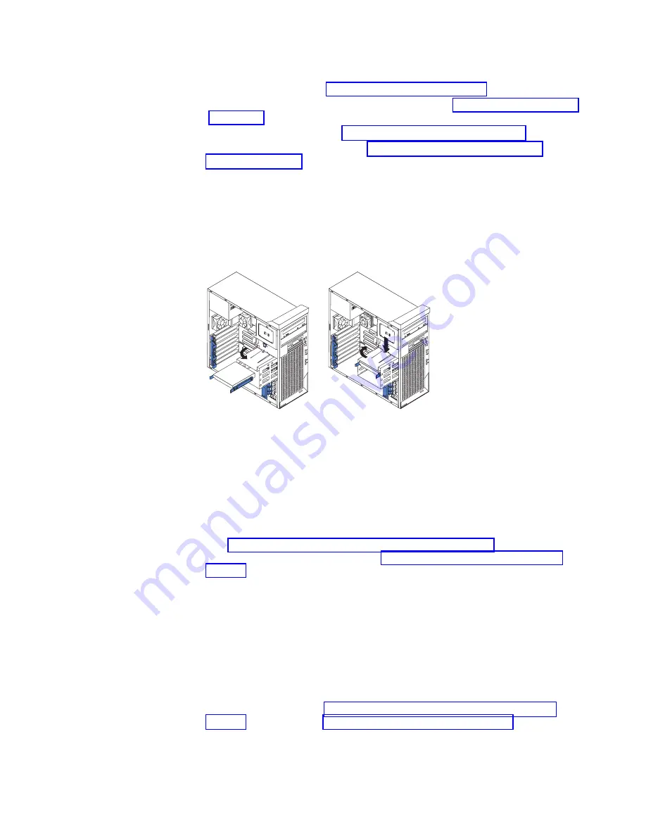
Complete the following steps to install a drive in bay 5, 6, or 7:
1. Follow the instructions in “Preinstallation steps” on page 23.
2. Turn off the computer and all attached devices (see “Turning off the computer”
on page 32); then, disconnect all power cords and external cables.
3. Remove the side cover (see “Removing the side cover” on page 17).
4. Remove the support bracket (see “Removing and installing the support
5. If your computer has hard disk drives preinstalled in the drive cage, disconnect
the power and signal cables from the rear of the drives.
6. Grasp the drive cage and rotate the cage out of the computer until it locks into
place with the drive-cage retention tab. The open ends of the drive slots and
installed drives will face you. Ensure that the drive cage locks into place over
the drive-cage retention tab by rotating the drive cage all the way out of the
computer.
13
94
13
94
7. Attach the blue guide rails to the side of the drive using the screws that are
provided. If you obtained your optional drive from IBM, the guide rails are blue
plastic.
8. Slide the drive into the drive cage until the plastic tabs on the drive guide rails
lock into place in the drive cage. Clear any cables that might impede the
replacement of the drive cage.
9. Determine whether the new drive is an IDE or SCSI device; then, connect one
end of the appropriate signal cable into the back of the drive and the other end
of this cable into the appropriate IDE or SCSI connector on the system board.
See “Power and signal cables for internal drives” on page 26 for additional
information about cabling drives and “System-board internal connectors” on
page 13 for the location of IDE and SCSI connectors on the system board. If
there are open connectors on the cables connecting existing IDE or SCSI
drives, these cables can be used to connect the new drive.
10. Route the signal cable so that it does not block the airflow to the rear of the
drives or over the microprocessor.
11. Connect the power cable to the back of the drive. The connectors are keyed
and can be inserted only one way.
12. Push the drive cage outward, and press in on the drive-cage release tab; then,
rotate the drive cage back into the computer.
13. If you have other options to install or remove, do so now; otherwise, replace
the support bracket (see “Removing and installing the support bracket” on
page 18) and then go to “Completing the installation” on page 29.
Chapter 2. Installing the hardware
25
Содержание IntelliStation M Pro 6219
Страница 3: ...IBM IntelliStation M Pro Type 6219 Installation Guide SC59 P566 30...
Страница 14: ...23 50 110 50 110 23 50 50 xii IBM IntelliStation M Pro Type 6219 Installation Guide...
Страница 15: ...23 50 50 23 50 110 50 110 50 Kg 50 23 Safety xiii...
Страница 16: ...23 50 110 50 110 23 50 110 50 110 23 50 50 xiv IBM IntelliStation M Pro Type 6219 Installation Guide...
Страница 17: ...23 50 110 50 110 23 50 110 50 110 23 50 50 110 Safety xv...
Страница 18: ...23 50 110 50 110 23 50 110 50 110 Instru o 23 xvi IBM IntelliStation M Pro Type 6219 Installation Guide...
Страница 20: ...xviii IBM IntelliStation M Pro Type 6219 Installation Guide...
Страница 28: ...8 IBM IntelliStation M Pro Type 6219 Installation Guide...
Страница 54: ...34 IBM IntelliStation M Pro Type 6219 Installation Guide...
Страница 58: ...38 IBM IntelliStation M Pro Type 6219 Installation Guide...
Страница 62: ...42 IBM IntelliStation M Pro Type 6219 Installation Guide...
Страница 70: ...50 IBM IntelliStation M Pro Type 6219 Installation Guide...
Страница 84: ...64 IBM IntelliStation M Pro Type 6219 Installation Guide...
Страница 90: ...70 IBM IntelliStation M Pro Type 6219 Installation Guide...
Страница 94: ......
Страница 95: ......
Страница 96: ...IBM Part Number 59P5663 Printed in the United States of America 59P5663...


