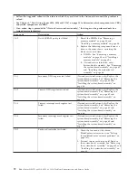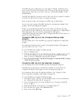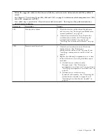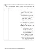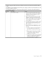
POST error codes
Use this information to diagnose and resolve POST error codes for the blade
server.
The following table describes the POST error codes and suggested actions to
correct the detected problems.
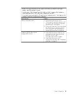
v
Follow the suggested actions in the order in which they are listed in the Action column until the problem is
solved.
v
See Chapter 4, “Parts listing, Types 8014, 8028 and 1916,” on page 25 to determine which components are CRUs
and which components are FRUs.
v
If an action step is preceded by “(Trained service technician only),” that step must be performed only by a
trained service technician.
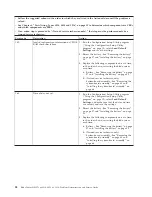
Error code
Description
Action
062
Three consecutive startup failures
1.
Run the Configuration/Setup Utility program
(“Using the Configuration/Setup Utility
program” on page 15), select
Load Default
Settings
, make sure that the date and time are
correct, and save the settings.
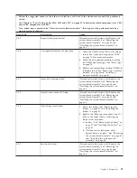
2.
Reseat the following components one at a time,
in the order shown, restarting the blade server
each time:
a.
Battery - See “Removing the battery” on page
57 and “Installing the battery” on page 58.
b.
(Trained service technician only)
Microprocessor - See “Removing a
microprocessor and heat sink” on page 60 and
“Installing a microprocessor and heat sink” on
page 62.
3.
Replace the following components one at a time,
in the order shown, restarting the blade server
each time:
a.
Battery - See “Removing the battery” on page
57 and “Installing the battery” on page 58.
b.
(Trained service technician only)
Microprocessor - See “Removing a
microprocessor and heat sink” on page 60 and
“Installing a microprocessor and heat sink” on
page 62.
c.
(Trained service technician only) System-board
assembly - See “Removing the system-board
assembly” on page 65 and “Installing the
system-board assembly” on page 66.
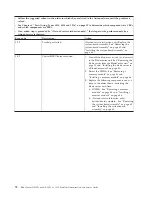
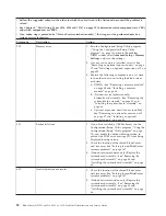
101
Timer tick interrupt failure
(Trained service technician only) Replace the
system-board assembly - See “Removing the
system-board assembly” on page 65 and “Installing
the system-board assembly” on page 66.
102
Timer 2 test failure
(Trained service technician only) Replace the
system-board assembly - See “Removing the
system-board assembly” on page 65 and “Installing
the system-board assembly” on page 66.
86
BladeCenter HS12 Type 8014, 8028 or 1916: Problem Determination and Service Guide
Содержание BladeCenter HS12 Type 1916
Страница 1: ...BladeCenter HS12 Type 8014 8028 or 1916 Problem Determination and Service Guide...
Страница 2: ......
Страница 3: ...BladeCenter HS12 Type 8014 8028 or 1916 Problem Determination and Service Guide...
Страница 36: ...24 BladeCenter HS12 Type 8014 8028 or 1916 Problem Determination and Service Guide...
Страница 186: ...174 BladeCenter HS12 Type 8014 8028 or 1916 Problem Determination and Service Guide...
Страница 190: ...178 BladeCenter HS12 Type 8014 8028 or 1916 Problem Determination and Service Guide...
Страница 198: ...186 BladeCenter HS12 Type 8014 8028 or 1916 Problem Determination and Service Guide...
Страница 203: ......
Страница 204: ...Part Number 60Y1601 Printed in USA 1P P N 60Y1601...

