IBM 9114-275 - IntelliStation POWER 275 Скачать руководство пользователя страница 50

Hot-Swap System Fans

This system supports hot plug and redundant cooling. The DASD and system electronics is cooled with
three system cooling fans. Before performing the following procedures, read “Safety Notices” on page vii.

Hot-Swap System Fan Removal

To remove a hot-swap fan, do the following:

1. Place the system into the service position as described in “Placing the Model 275 into the Service and

Operating Position” on page 26.

2. Remove the service access cover as described in “Service Access Cover Removal” on page 28

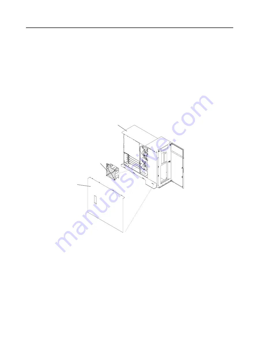
3. Locate the cooling fans, as shown in the following illustration.

4. Pull on the locking knob of the failing fan until you feel it unlock.

5. Pull on the locking knob of the failing fan again until you feel the fan pull loose from its connector.

6. Grasp the sheet metal lip of the fan and pull the fan towards the side that contains the locking knob.

7. Lift out the failing fan unit.

2

1

3

1

Model 275

2

Service Access Cover

3

Cooling Fan (Fan #1)

Hot-Swap System Fan Replacement

Notes:

1. On systems with Linux installed, you may be required to shut down and run AIX diagnostics to verify

the hot-swap repair.

2. This note applies only to systems running the AIX operating system. If a fan assembly is being

replaced for a redundant failure, after the service repair action is completed, ask the customer to check
the

crontab

file for any power/cooling warning messages. When a power or cooling error is

encountered, AIX adds an entry to the

crontab

file to

wall

a warning message every 12 hours, to

alert or remind the customer of the problem. Replacing the faulty part does not clear this

crontab

34

IntelliStation POWER 9114 Model 275 Installation Guide

Содержание 9114-275 - IntelliStation POWER 275

Страница 1: ...IntelliStation POWER 9114 Model 275 Installation Guide SA38 0634 00...

Страница 2: ......

Страница 3: ...IntelliStation POWER 9114 Model 275 Installation Guide SA38 0634 00...

Страница 4: ...to Information Development Department H6DS 905 6C006 11501 Burnet Road Austin Texas 78758 3493 To send comments electronically use this commercial internet address aix6kpub austin ibm com Any informa...

Страница 5: ...e Serial Devices Parallel Devices and ASCII Terminal 9 Step 13 Connect the Adapter Cables 10 Step 14 Are You Using an Ethernet Connection 11 Step 15 Connect the Power Cables to the System 12 Step 16 I...

Страница 6: ...ssembly 35 Removing the Fan Tray Assembly 35 Replacing the Fan Tray Assembly 37 Power Supply 38 Power Supply Removal 38 Power Supply Replacement 40 Installing a Power Supply 41 Media Drives Diskette C...

Страница 7: ...Appendix B Environmental Notices 65 Product Recycling and Disposal 65 Environmental Design 65 Acoustical Noise Emissions 65 Declared Acoustical Noise Emissions 65 Appendix C Notices 67 Appendix D Sys...

Страница 8: ...vi IntelliStation POWER 9114 Model 275 Installation Guide...

Страница 9: ...esponsibility of the customer to ensure that the outlet is correctly wired and grounded to prevent an electrical shock Before installing or removing signal cables ensure that the power cables for the...

Страница 10: ...DANGER To prevent electrical shock hazard disconnect all power cables from the electrical outlet before relocating the system D01 viii IntelliStation POWER 9114 Model 275 Installation Guide...

Страница 11: ...laser certification numbers and approval information CAUTION All IBM laser modules are designed so that there is never any human access to laser radiation above a class 1 level during normal operatio...

Страница 12: ...x IntelliStation POWER 9114 Model 275 Installation Guide...

Страница 13: ...ges or component failures must verify the accuracy of operations performed and data saved or transmitted by the system at or near the time of the outage or failure In addition users must establish pro...

Страница 14: ...xii IntelliStation POWER 9114 Model 275 Installation Guide...

Страница 15: ...ons click Hardware documentation v To view information about the accessibility features of Eserver pSeries hardware and the AIX operating system click AIX and pSeries accessibility References to AIX O...

Страница 16: ...can be used in this system Ergonomic Information After you have set up your system we encourage you to visit the Healthy Computing Web site Good ergonomic practice is important to get the most from yo...

Страница 17: ...procedures in this chapter Step 1 Check Your Inventory IntelliStation POWER 9114 Model 275 h Books CD ROM and Other Media h About Your Machine Document h Power Cables 1 standard 2 optional h 9 Pin to...

Страница 18: ...ed from the previous page h Display Cable optional and Cable Toroid optional h Keyboard optional Wrist Palm Rest optional h Mouse optional hModel 275 h Power On Guard 2 IntelliStation POWER 9114 Model...

Страница 19: ...ty of the customer to ensure that the outlet is correctly wired and grounded to prevent an electrical shock Before installing or removing signal cables ensure that the power cables for the system unit...

Страница 20: ...ift the system unit by yourself v Displays and ASCII terminals can weigh as much as 35 kg 77 pounds Use caution when lifting or moving the display or ASCII terminal v Leave enough space around the sys...

Страница 21: ...Serial Devices Parallel Devices and ASCII Terminal on page 9 2 If you are using a graphics display with a keyboard and mouse continue with Step 9 Attach the Display Cable Toroid on page 6 If you order...

Страница 22: ...the cable for your display does not include a toroid locate the toroid shipped with your system and follow the installation instructions included with the toroid 1 Display Cable Toroid 6 IntelliStatio...

Страница 23: ...ble Toroid on page 6 connect the graphics display cable to the back of the display and to the graphics adapter connector For the locations of installed adapters consult the About Your Machine document...

Страница 24: ...otices on page 3 If a wrist or palm rest was included with your keyboard and you want to attach it refer to the keyboard documentation for installation instructions As shown in the following illustrat...

Страница 25: ...terminal connect it through an external modem to serial connector S1 and connect a local ASCII terminal to serial connector S2 or serial connector S3 If you have a local ASCII terminal or a single se...

Страница 26: ...our system to run HACMP with a UPS attached you must connect the HACMP cable to serial port S2 and the UPS cable to serial port S3 Do not run a UPS connected to serial port S2 If you decide to disconn...

Страница 27: ...page 12 To connect the Ethernet cable do the following Note The twisted pair connector is compatible with the IEEE 802 3 Ethernet network 10 100 1000 Base T link 1 Connect the twisted pair cable to o...

Страница 28: ...power cable to the power receptacle A second power receptacle is present when a second redundant power supply has been added to the system drawer See the following illustration 1 Primary Power Supply...

Страница 29: ...r system Step 17 Install the Power On Button Guard To help prevent accidental power on or power off operations ensure that the power on button guard is installed Snap the power on button guard into pl...

Страница 30: ...rdware is Now Set Up Arrange your system unit and attached devices so that you can use them comfortably If an operating system has been preinstalled in your system continue to Step 20 Start Your Model...

Страница 31: ...e 9 Serial Number Label 3 Press the power on button on the operator panel After you press the power on button located on the operator panel observe the following a The power LED begins to blink visibl...

Страница 32: ...ds the following information and is aware of the options to access the documentation for the new system Hardware Documentation IBM Eserver pSeries hardware publications are available online To access...

Страница 33: ...g this procedure v This procedure requires a display attached to a graphics adapter or an ASCII terminal attached to the S1 or S2 port Does the system have online AIX diagnostics preinstalled YES Go t...

Страница 34: ...ays on the firmware console and before the last POST indicator speaker displays press the numeric 5 key on either the directly attached keyboard or the ASCII terminal to indicate that a service mode b...

Страница 35: ...server but Cstate has not been set no data will be returned 0042 053 lsnim there is no NIM object named ClientName The client is not registered on the NIM server Client Configuration and Booting Stand...

Страница 36: ...to the SMS Main screen 2 Select Select Boot Options 3 Select Install or Boot a Device 4 On the Select Device Type screen select Network 5 Set the network parameters for the adapter from which you wan...

Страница 37: ...stating No trouble was found v The A Problem Was Detected On Time Stamp menu displays with either a service request number SRN or an error code Make a note of any codes displayed on the display or op...

Страница 38: ...r person is the system administrator deliver this book to the system administrator when the installation is complete Ensure that the system administrator reads the following information and is aware o...

Страница 39: ...e customer to ensure that the outlet is correctly wired and grounded to prevent an electrical shock Before installing or removing signal cables ensure that the power cables for the system unit and all...

Страница 40: ...ions and Task List The following table provides a listing that allows you to quickly locate the appropriate procedures Option Task Option Task Name and Page Location Adapters PCI Adapters on page 29 B...

Страница 41: ...devices to Off Starting the System To power on the system do the following 1 Open the bezel door 2 Ensure that the power is connected the system unit Before you press the power on button on your oper...

Страница 42: ...ystem 2 Lift the bezel door release tab located at the bottom of the door in order to clear the post 3 Gently swivel the bottom of the door forward out past the bottom of the system 4 Pull the door do...

Страница 43: ...Put the bezel and bezel door in a safe place 1 Model 275 4 Front Door 2 Bezel release lever 5 Lower Bezel Locking Tab Quantity 2 3 Front Bezel 6 Lower Bezel Retaining Slots Quantity 2 Front Bezel Rep...

Страница 44: ...rating the system for extended periods of time over 30 minutes with the cover removed might damage system components 1 Model 275 3 Service Access Cover 2 Front Chassis Ledge 4 Thumbscrews Service Acce...

Страница 45: ...n the system as described in Stopping the System on page 25 3 Disconnect the power source to the system Note This system may be equipped with a second power supply Before continuing with this procedur...

Страница 46: ...make note of how the back edge of the adapter slides into the molded grooves located on the back wall of the PCI adapter slots 1 Service Access Cover 2 PCI Adapters 3 System Unit 30 IntelliStation POW...

Страница 47: ...corners and remove it from the system Store the adapter in a safe place 12 If you do not plan to install another adapter into the vacated slot seal the expansion slot using an expansion slot cover and...

Страница 48: ...for information regarding slot restrictions for adapters that can be used in this system 6 If necessary remove the adapter expansion slot shield 7 Before handling any card board or memory DIMM be sur...

Страница 49: ...the unlocked position 14 If you have other options to install refer to Options and Task List on page 24 If you do not have other options to install continue on to the next step 15 Replace the service...

Страница 50: ...pull loose from its connector 6 Grasp the sheet metal lip of the fan and pull the fan towards the side that contains the locking knob 7 Lift out the failing fan unit 2 1 3 1 Model 275 2 Service Acces...

Страница 51: ...rating Position on page 26 Fan Tray Assembly The three system cooling fans rest in a fan tray The fans can remain in the tray while it is removed or replaced Removing the Fan Tray Assembly To remove t...

Страница 52: ...1 Model 275 4 LED Light Pipe Plate 2 Guide Rails 5 Latch Buttons 3 Latch Tabs 6 Fan Tray Assembly 7 Service Access Cover 36 IntelliStation POWER 9114 Model 275 Installation Guide...

Страница 53: ...lock 5 Latch the LED light pipe plate over the LED light pipes Be sure to align the LED light pipes with the appropriate holes in the LED light pipe plate 6 If your system does not contain a SCSI medi...

Страница 54: ...e bezel door 2 Shut down the system as described in Stopping the System on page 25 3 Remove the service access cover as described in Service Access Cover Removal on page 28 4 Remove the power cable fr...

Страница 55: ...Power Supply 1 Primary 2 Power Supply Filler Panel 5 Power Supply Release Handle 3 System Unit 8 After the power supply is released from its connector pull the power supply straight out from the syst...

Страница 56: ...into the connector The spring latch located on the underside of each handle will snap into place indicating that the power supply is seated correctly and locked into position 1 Power supply 4 Fault LE...

Страница 57: ...optional power supply bay 6 Lower the power supply release handles carefully pressing the power supply into the connector The spring latch located on the underside of each handle will snap into place...

Страница 58: ...ay Before performing this procedure read the following v Safety Notices on page vii v Laser Safety Information on page ix Slimline Media A Slimline diskette drive must be placed in the right drive slo...

Страница 59: ...CSI Media Device Installation or Replacement To replace a media device do the following 1 Before handling any card board or memory DIMM be sure to use your electrostatic discharge strap to minimize st...

Страница 60: ...is from the system chassis Note If you are servicing a Model 275 the operator panel will remain in the media bay chassis while it is removed 1 Model 275 2 Media Bay Chassis 3 Front Bezel Replacing the...

Страница 61: ...rom the slot you want to use 2 Remove the disk drive bezel plug from the front of the filler panel 3 Remove the disk drive bezel from the front edge of the filler panel 4 Attach the disk drive bezel t...

Страница 62: ...ive as described in Hot Plug Disk Drives on page 47 2 Remove the disk drive bezel from the front of the filler or disk drive 3 Attach the disk drive bezel to the front edge of the filler panel or repl...

Страница 63: ...nter at http publib16 boulder ibm com pseries en_US infocenter base Select AIX documentation The AIX Documentation CD contains the base set of publications for the operating system including system ma...

Страница 64: ...t the top of the screen 7 Press the F3 key enough times to return to first smitty menu Then select System Storage Management Physical and Logical Storage 8 Select Logical Volume Manager and press Ente...

Страница 65: ...fore removing the disk ensure all data has been saved 2 Deconfigure the drive you are removing from the system See Deconfiguring Removing a Disk Drive on page 47 3 Open the front bezel door 4 Locate t...

Страница 66: ...1 Model 275 2 Disk Drive 3 Disk Drive Release Handle 12 Press F10 to exit smitty 50 IntelliStation POWER 9114 Model 275 Installation Guide...

Страница 67: ...g any hot pluggable PCI adapters A system with Linux installed must be shut down and powered off before replacing any PCI adapter assigned to a Linux partition Use the non hot pluggable adapter proced...

Страница 68: ...over Removal on page 28 5 Remove the fan tray assembly as described in Removing the Fan Tray Assembly on page 35 6 Before handling any card board or DIMM be sure to use your electrostatic discharge st...

Страница 69: ...le to the chassis hooks and align the hooks with the guides on the disk drive backplane 6 Tip the disk drive backplane forward onto the chassis hooks Firmly press the disk drive backplane into the con...

Страница 70: ...n Placing the Model 275 into the Service and Operating Position on page 26 3 Remove the service access cover as described in Service Access Cover Removal on page 28 4 Remove the fan tray assembly as d...

Страница 71: ...fully grasp the memory DIMM along two edges and align the connector 12 Insert the memory card firmly into the connector 13 Secure the memory DIMM with the locking tabs located at each end of the DIMM...

Страница 72: ...ply as described in Power Supply Removal on page 38 7 If necessary to access DIMMs on the system backplane remove the service processor assembly as described in Service Processor Assembly on page 57 8...

Страница 73: ...ces on page 24 8 Locate the service processor assembly as shown in the following illustration 9 Unlock the two camming latches on top of the service processor assembly 10 Release the service processor...

Страница 74: ...bed in Service Access Cover Replacement on page 28 8 Return the system to the operating position as described in Placing the Model 275 into the Service and Operating Position on page 26 9 Reconnect ca...

Страница 75: ...ge 57 5 Locate the battery on the service processor assembly 6 Use your fingernail to pry the battery out of its plastic mount After the bottom of the battery has cleared the top edge of the plastic m...

Страница 76: ...Center at http publib16 boulder ibm com pseries en_US infocenter base Select AIX documentation The AIX Documentation CD contains the base set of publications for the operating system including system...

Страница 77: ...user is encouraged to try to correct the interference by one or more of the following measures v Reorient or relocate the receiving antenna v Increase the separation between the equipment and receiver...

Страница 78: ...and built to comply with IEC Standard 950 United Kingdom Telecommunications Safety Requirements This equipment is manufactured to the International Safety Standard EN60950 and as such is approved in...

Страница 79: ...ct is aimed to be used in a domestic environment When used near a radio or TV receiver it may becaome the cause of radio interference Read the instructions for correct handling Radio Protection for Ge...

Страница 80: ...64 IntelliStation POWER 9114 Model 275 Installation Guide...

Страница 81: ...ide and other battery packs from IBM Equipment For information on proper disposal of these batteries please contact IBM at 1 800 426 4333 Have the IBM part number listed on the battery available prior...

Страница 82: ...66 IntelliStation POWER 9114 Model 275 Installation Guide...

Страница 83: ...untry where such provisions are inconsistent with local law THIS MANUAL IS PROVIDED AS IS WITHOUT WARRANTY OF ANY KIND EITHER EXPRESSED OR IMPLIED INCLUDING BUT NOT LIMITED TO THE IMPLIED WARRANTIES O...

Страница 84: ...68 IntelliStation POWER 9114 Model 275 Installation Guide...

Страница 85: ...fication information Identification Numbers Record and retain the following information Product Name IntelliStation POWER 9114 Model 275 Serial Number Key Serial Number The system unit s serial number...

Страница 86: ...vice Memory Card 1 Memory DIMM 1 J3B U0 1 P1 M1 5 Memory DIMM 5 J0A U0 1 P1 M5 2 Memory DIMM 2 J3A U0 1 P1 M2 6 Memory DIMM 6 J0B U0 1 P1 M6 3 Memory DIMM 3 J2B U0 1 P1 M3 7 Memory DIMM 7 J1A U0 1 P1...

Страница 87: ...____________________________ Expansion Slot 2 ______________________________________________ Expansion Slot 1 ______________________________________________ Parallel Port _____________________________...

Страница 88: ...CSI ID 8 Notes 1 The SCSI bus IDs are the recommended values and indicate how the IDs are set when the system is shipped from the factory Field installations might not comply with these recommendation...

Страница 89: ...ine is entered the screen moves down one line Auto LF Off Off Off For the On setting pressing the Return key moves the cursor to the first character position of the next line For the Off setting press...

Страница 90: ...character as the line turnaround character Interface EIA 232 EIA 232 EIA 232 Uses the EIA 232 interface protocol Line control IPRTS IPRTS IPRTS Uses the permanent request to send IPRTS signal to commu...

Страница 91: ...the Insert key is pressed Additional Printer Attributes The following printer attributes are for a printer attached to the 3151 3161 and 3164 terminals Printer Setup Attributes 3151 11 31 41 Settings...

Страница 92: ...76 IntelliStation POWER 9114 Model 275 Installation Guide...

Страница 93: ...rmware Update Using a Locally Available Image To update the system firmware using a locally available image perform the following steps 1 Log in as root user 2 If the directory tmp fwupdate does not e...

Страница 94: ...ttention On some systems the message Wait for rebooting before stopping may display on the system console Do not turn off the system until the system has fully rebooted to the AIX login prompt If a sh...

Страница 95: ...one NIM server 18 stopping 21 verifying hardware 17 disk drive backplane 52 disk drives deconfiguring 47 display type 5 documentation 16 22 documentation continued accessing 16 AIX 16 19 22 35 47 48 5...

Страница 96: ...I 29 battery replacing 59 bezel door 26 bezel door removal 26 bezel door replacement 26 bezel removal 27 bezel replacement 27 bezels 27 CD ROM drive 42 covers 28 devices handling static sensitive 24 d...

Страница 97: ...ay 6 trademarks xiv TTY terminal attributes general 73 TTY terminal attributes required for diagnostics 73 V verification system 16 21 additional 21 verifying hardware operation 17 W Web sites 4 AIX d...

Страница 98: ...82 IntelliStation POWER 9114 Model 275 Installation Guide...

Страница 99: ...is Very Satisfied Satisfied Neutral Dissatisfied Very Dissatisfied Accurate h h h h h Complete h h h h h Easy to find h h h h h Easy to understand h h h h h Well organized h h h h h Applicable to you...

Страница 100: ...S 905 6C006 11501 Burnet Road Austin TX 78758 3493 _ _ _ _ _ _ _ _ _ _ _ _ _ _ _ _ _ _ _ _ _ _ _ _ _ _ _ _ _ _ _ _ _ _ _ _ _ _ _ _ _ _ _ _ _ _ _ _ _ _ _ _ _ _ _ _ _ _ _ _ _ _ _ _ _ _ _ _ _ _ _ _ _ _ _...

Страница 101: ......

Страница 102: ...Part Number 00P5944 Printed in U S A SA38 0634 00 1P P N 00P5944...

Отзывы: