Attention:
To
avoid
damage
and
to
ensure
proper
server
operation,
review
the
following
information
before
you
install
a
microprocessor:
v
Make
sure
that
the
microprocessors
are
the
same
type,
have
the
same
cache
size,
and
have
the
same
clock
speed.
v
See
the
ServerProven
list
at
http://www.ibm.com/pc/us/compat/
for
a
list
of
microprocessors
that
are
supported
by
the
server.
The
following
procedure
describes
installation
of
a
microprocessor.
Microprocessors
should
be
removed
only
by
qualified
service
technicians
(see
“Removing
a
microprocessor”
on
page
54).
Complete
the
following
steps
to
install
a
microprocessor:
1.
Read
“Safety
information”
on
page
101
and
“Installation
guidelines”
on
page
25.
2.
Turn
off
the
server
and
all
attached
peripheral
devices.
Disconnect
all
power
cords;
then,
disconnect
all
external
signal
cables
from
the
server.
3.
Remove
the
server
from
the
rack;
then,
remove
the
server
cover
(see
“Removing
the
cover
and
bezel”
on
page
27).
Determine
the
socket
where
the
microprocessor
is
to
be
installed.
Attention:
v
Avoid
touching
the
components
and
gold-edge
connectors
on
the
microprocessor.
Make
sure
that
the
microprocessor
is
completely
and
correctly
seated
in
the
socket.
Incomplete
insertion
might
cause
damage
to
the
system
board
or
to
the
microprocessor.
v
When
you
handle
static-sensitive
devices,
take
precautions
to
avoid
damage
from
static
electricity.
For
information
about
handling
these
devices,
see
“Handling
static-sensitive
devices”
on
page
25.
Note:
A
new
microprocessor
comes
in
a
kit
with
a
heat
sink.
4.
If
you
are
installing
a
microprocessor
in
the
microprocessor
2
socket,
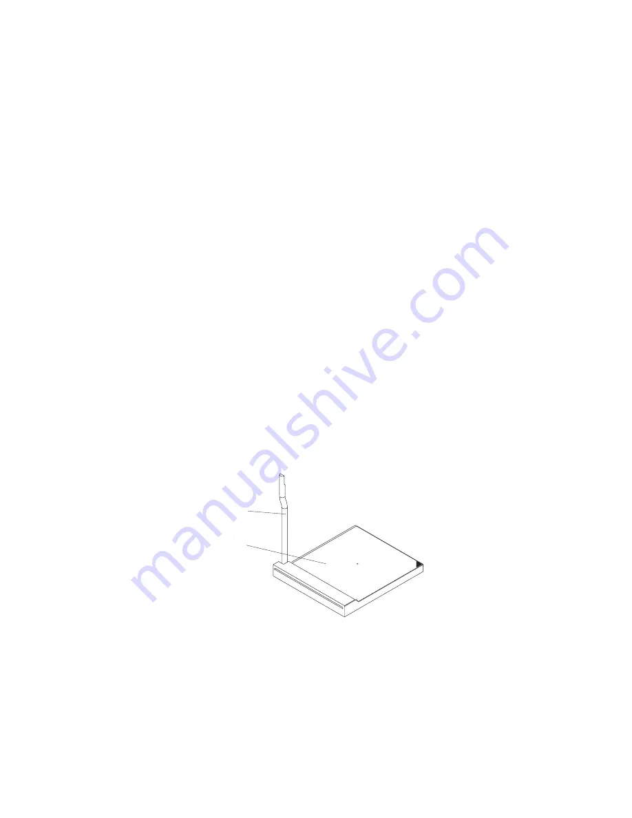
lift
the
microprocessor-locking
lever
to
the
open
position.
Microprocessor-
locking lever
Microprocessor
socket
5.
Install
the
microprocessor:
a.
Touch
the
static-protective
package
containing
the
new
microprocessor
to
any
unpainted
metal
surface
on
the
server;
then,
remove
the
microprocessor
from
the
package.
b.
Position
the
microprocessor
over
the
microprocessor
socket
as
shown
in
the
following
illustration.
Carefully
press
the
microprocessor
into
the
socket.
Attention:
To
avoid
bending
the
pins
on
the
microprocessor,
do
not
use
excessive
force
when
pressing
it
into
the
socket.
40
Eserver
325
Type
8835:
Hardware
Maintenance
Manual
and
Troubleshooting
Guide
Содержание 8835 - Eserver 325 - 1 GB RAM
Страница 1: ...Eserver 325 Type 8835 Hardware Maintenance Manual and Troubleshooting Guide ERserver...
Страница 2: ......
Страница 3: ...Eserver 325 Type 8835 Hardware Maintenance Manual and Troubleshooting Guide ERserver...
Страница 6: ...iv Eserver 325 Type 8835 Hardware Maintenance Manual and Troubleshooting Guide...
Страница 10: ...viii Eserver 325 Type 8835 Hardware Maintenance Manual and Troubleshooting Guide...
Страница 22: ...12 Eserver 325 Type 8835 Hardware Maintenance Manual and Troubleshooting Guide...
Страница 60: ...50 Eserver 325 Type 8835 Hardware Maintenance Manual and Troubleshooting Guide...
Страница 82: ...72 Eserver 325 Type 8835 Hardware Maintenance Manual and Troubleshooting Guide...
Страница 108: ...98 Eserver 325 Type 8835 Hardware Maintenance Manual and Troubleshooting Guide...
Страница 123: ...Appendix B Related service information 113...
Страница 124: ...114 Eserver 325 Type 8835 Hardware Maintenance Manual and Troubleshooting Guide...
Страница 125: ...Appendix B Related service information 115...
Страница 126: ...116 Eserver 325 Type 8835 Hardware Maintenance Manual and Troubleshooting Guide...
Страница 127: ...Appendix B Related service information 117...
Страница 128: ...118 Eserver 325 Type 8835 Hardware Maintenance Manual and Troubleshooting Guide...
Страница 129: ...Appendix B Related service information 119...
Страница 142: ...132 Eserver 325 Type 8835 Hardware Maintenance Manual and Troubleshooting Guide...
Страница 143: ...Appendix B Related service information 133...
Страница 144: ...134 Eserver 325 Type 8835 Hardware Maintenance Manual and Troubleshooting Guide...
Страница 145: ...Appendix B Related service information 135...
Страница 146: ...136 Eserver 325 Type 8835 Hardware Maintenance Manual and Troubleshooting Guide...
Страница 147: ...Appendix B Related service information 137...
Страница 152: ...142 Eserver 325 Type 8835 Hardware Maintenance Manual and Troubleshooting Guide...
Страница 158: ...148 Eserver 325 Type 8835 Hardware Maintenance Manual and Troubleshooting Guide...
Страница 163: ......
Страница 164: ...Part Number 90P3053 Printed in USA 1P P N 90P3053...


